Product Description
Product Description
Product Description
| Item | Shaft, axle |
| Application | Cranes, Railway way, mineral Machinery, hydraulic Machinery, Spare parts etc. |
| Design | Can be at the customer’ request, tailor-made, at customer’s design |
| Material | Stainless Steel or Carbon Steel, such as 45#, 65# SAE4140, SAE4150, SAE4160, 42CrMo, stainless steel 410, stainless steel 304, or other required steel |
| Size | Diameter 80mm to 2000mm. Length max.in 6000mm |
| Minimum order | 1Pcs |
Product Real Shot
Manufacturing Process
- Free forged or module forged
- Rough machining process, to remove the surface forged oxidized black leather.
- 100% Ultrasonic Test ASTMA388
- Heat Treatment according to request, Normalized, Quenched, Tempered….
- Hardness test
- Finishing Process to the dimensional state required by the drawing.
- 100% Magnetic Test ASTM E709 and 100% dimensional test
- Painting or oil protecting TECTYL 506 or similiar
- Packing with boxes
Data Needed for Quotation
– Your own drawing
– Your requirement on material and necessary dimensional data
– Ask for recommend
Company Profile
ZheJiang CHINAMFG Machinery Co., Ltd., established in the year of 2012, is a professional supplier of material handling equipment, OEM machinery parts, various forging parts and casting parts.
Ebon’s products scope: cranes, hoists, magnets, grabs, hooks, wheels, drums, axles, lifting beams,bearing box, bearings, couplings,flanges etc. They are applied in wide range of field: Machinery, Mining, Hydro power Transportation, Construction…..
CHINAMFG has 5 reliable manufacturing factories to make sure stable supply and fast delivery for your business.
Our products are also exported to USA, Britain, Japan, South Korea, Russia, Indonesia, Thailand, India, Vietnam, Canada, Argentina, Paraguay etc more than 50 countries.
CHINAMFG team is loyal and committed to your success, and firmly believes that our products and services will increase the value and effectiveness of your business with following characters:
-Professional sales team, market promotion team and logistics team with more then 10 years experience .
-Loyal and Responsible Characters
-Efficient Work, Fast Response
-Responsible Quality Control Team
-Video the manufacturing process, the testing, and packing before delivery
1.Q: How about your delivery time?
A: Generally, it will take 7-30 days after receiving your advance payment. The specific delivery time depends on the items, transportation ways and the quantity of your order.
2.Q: Can you produce according to the samples?
A: Yes, we can produce by your samples or technical drawings.
3.Q: Do you test all your goods before delivery?
A: Yes, we have 100% Ultrasonic test, Magnetic test or Liquid Penetration test before delivery
4.Q: How do you make our business long-term and good relationship?
A: (1) We keep good quality and competitive price to ensure our customers benefit ;
(2) We respect every customer as our friend and we sincerely do business and make friends with them, no matter where they come from.
5.Q: I can’t see the goods or touch the goods, how can I deal with the risk involved?
A: Our quality management system conforms to the requirement of ISO 9001:2015 verified by DNV. We are absolutely worth your trust. We can accept trial order to enhance mutual trust.
/* January 22, 2571 19:08:37 */!function(){function s(e,r){var a,o={};try{e&&e.split(“,”).forEach(function(e,t){e&&(a=e.match(/(.*?):(.*)$/))&&1
| Processing Object: | Metal |
|---|---|
| Molding Style: | Forging |
| Molding Technics: | Pressure Casting |
| Application: | Machinery Parts |
| Material: | Steel |
| Heat Treatment: | Quenching |
| Customization: |
Available
| Customized Request |
|---|

How do spline shafts handle variations in torque and rotational force?
Spline shafts are designed to handle variations in torque and rotational force in mechanical systems. Here’s a detailed explanation:
1. Interlocking Splines:
Spline shafts have a series of interlocking splines along their length. These splines engage with corresponding splines on the mating component, such as gears or couplings. The interlocking design ensures a secure and robust connection, capable of transmitting torque and rotational force.
2. Load Distribution:
When torque is applied to a spline shaft, the load is distributed across the entire engagement surface of the splines. This helps to minimize stress concentrations and prevents localized wear or failure. The load distribution capability of spline shafts allows them to handle variations in torque and rotational force effectively.
3. Material Selection:
Spline shafts are typically made from materials with high strength and durability, such as alloy steels. The material selection is crucial in handling variations in torque and rotational force. It ensures that the spline shaft can withstand the applied loads without deformation or failure.
4. Spline Profile:
The design of the spline profile also contributes to the handling of torque variations. The spline profile determines the contact area and the distribution of forces along the splines. By optimizing the spline profile, manufacturers can enhance the load-carrying capacity and improve the ability of the spline shaft to handle variations in torque.
5. Surface Finish and Lubrication:
Proper surface finish and lubrication play a crucial role in the performance of spline shafts. A smooth surface finish reduces friction and wear, while suitable lubrication minimizes heat generation and ensures smooth operation. These factors help in handling variations in torque and rotational force by reducing the impact of friction and wear on the spline engagement.
6. Design Considerations:
Engineers take several design considerations into account to ensure spline shafts can handle variations in torque and rotational force. These considerations include appropriate spline dimensions, tooth profile geometry, spline fit tolerance, and the selection of mating components. By carefully designing the spline shaft and its mating components, engineers can optimize the system’s performance and reliability.
7. Overload Protection:
In some applications, spline shafts may be equipped with overload protection mechanisms. These mechanisms, such as shear pins or torque limiters, are designed to disconnect the drive temporarily or slip when the torque exceeds a certain threshold. This protects the spline shaft and other components from damage due to excessive torque.
Overall, spline shafts handle variations in torque and rotational force through their interlocking splines, load distribution capability, appropriate material selection, optimized spline profiles, surface finish, lubrication, design considerations, and, in some cases, overload protection mechanisms. These features ensure efficient torque transmission and enable spline shafts to withstand the demands of various mechanical systems.

Can spline shafts be applied in aerospace and aviation equipment?
Yes, spline shafts are commonly applied in aerospace and aviation equipment due to their ability to transmit torque and provide precise rotational motion. Here’s how spline shafts are used in the aerospace and aviation industry:
1. Aircraft Engines:
Spline shafts are utilized in aircraft engines for various purposes. They can be found in the engine’s accessory gearbox, where they transmit torque from the engine to drive auxiliary components such as fuel pumps, hydraulic pumps, generators, and engine starters. Spline shafts are also present in the engine’s variable geometry systems, which control the position of components like variable stator vanes or variable inlet guide vanes.
2. Flight Control Systems:
Spline shafts play a vital role in aircraft flight control systems. They are employed in the actuators and control mechanisms that operate the flaps, ailerons, elevators, rudders, and other control surfaces. Spline shafts enable precise and efficient transfer of control inputs from the cockpit to the respective control surfaces, contributing to the maneuverability and stability of the aircraft.
3. Landing Gear:
Spline shafts are used in the landing gear systems of aircraft. They can be found in components such as the landing gear actuator, which extends and retracts the landing gear, and the steering mechanism that controls the nose wheel. Spline shafts in landing gear systems need to withstand high loads, provide reliable operation, and ensure precise movement for safe and smooth landings and takeoffs.
4. Helicopter Rotors:
Helicopters rely on spline shafts in the main rotor assembly. The main rotor shaft, which transfers power from the helicopter’s engine to the rotor blades, often incorporates splines to ensure a secure connection and efficient torque transmission. Spline shafts are critical for maintaining stable and precise rotation of the rotor blades, allowing for controlled lift and maneuverability.
5. Auxiliary Systems:
Spline shafts are also applied in various auxiliary systems in aerospace and aviation equipment. These include systems such as power transmission for onboard generators, environmental control systems, fuel control systems, and hydraulic systems. Spline shafts in these applications contribute to the reliable operation and efficient functioning of the auxiliary equipment.
In aerospace and aviation applications, spline shafts are designed to meet stringent requirements for strength, durability, precision, and weight reduction. They are often made from high-strength materials such as titanium or alloy steel to withstand the demanding operating conditions and weight constraints of aircraft. Additionally, advanced manufacturing techniques are employed to ensure the dimensional accuracy and quality of spline shafts for critical aerospace applications.
The use of spline shafts in aerospace and aviation equipment enables precise control, efficient power transmission, and reliable operation, contributing to the safety, performance, and functionality of aircraft and related systems.
In which industries are spline shafts typically used?
Spline shafts find applications in a wide range of industries where torque transmission, relative movement, and load distribution are critical. Here’s a detailed explanation:
1. Automotive Industry:
The automotive industry extensively uses spline shafts in various components and systems. They are found in transmissions, drivelines, steering systems, differentials, and axle assemblies. Spline shafts enable the transmission of torque, accommodate relative movement, and ensure efficient power transfer in vehicles.
2. Aerospace and Defense Industry:
Spline shafts are essential in the aerospace and defense industry. They are used in aircraft landing gear systems, actuation mechanisms, missile guidance systems, engine components, and rotor assemblies. The aerospace and defense sector relies on spline shafts for precise torque transfer, relative movement accommodation, and critical control mechanisms.
3. Industrial Machinery and Equipment:
Spline shafts are widely employed in industrial machinery and equipment. They are used in gearboxes, machine tools, pumps, compressors, conveyors, printing machinery, and packaging equipment. Spline shafts enable torque transmission, accommodate misalignments and vibrations, and ensure accurate movement and synchronization of machine components.
4. Agriculture and Farming:
The agriculture and farming industry extensively uses spline shafts in equipment such as tractors, harvesters, and agricultural implements. Spline shafts are found in power take-off (PTO) units, transmission systems, hydraulic mechanisms, and steering systems. They enable torque transfer, accommodate relative movement, and provide flexibility in agricultural machinery.
5. Construction and Mining:
In the construction and mining industries, spline shafts are used in equipment such as excavators, loaders, bulldozers, and drilling rigs. They are found in hydraulic systems, power transmission systems, and articulated mechanisms. Spline shafts facilitate torque transmission, accommodate misalignments, and enable efficient power transfer in heavy-duty machinery.
6. Marine and Offshore:
Spline shafts have applications in the marine and offshore industry. They are used in propulsion systems, thrusters, rudders, winches, and marine pumps. Spline shafts enable torque transmission in marine vessels and offshore equipment, accommodating axial and radial movement, and ensuring reliable power transfer.
7. Energy and Power Generation:
Spline shafts are utilized in the energy and power generation sector. They are found in turbines, generators, compressors, and other rotating equipment. Spline shafts enable torque transmission and accommodate relative movement in power generation systems, ensuring efficient and reliable operation.
8. Rail and Transportation:
Spline shafts are employed in the rail and transportation industry. They are found in locomotives, railcar systems, and suspension mechanisms. Spline shafts enable torque transfer, accommodate movement and vibrations, and ensure precise control in rail and transportation applications.
These are just a few examples of the industries where spline shafts are typically used. Their versatility, torque transmission capabilities, and ability to accommodate relative movement make them vital components in various sectors that rely on efficient power transfer, flexibility, and precise control.


editor by CX 2024-03-03
China wholesaler Metal Spur Gear Shaft with Spline for Cylindrical Gearboxes
Product Description
| Tooth trace | Involute |
| material | 18Cr2Ni4WA |
| Process | Forging, carburization and teeth grinding, spline shaping |
| Pressure angle | Gear Part 20°, Spline 30°P |
| Quality level | Gear part DIN 6; Spline part GB3478 grade 6. |
| Type | Mn=5, Z=16, a=20°; Mn=2.5, Z=17, a=30°P; Mn=2.5, Z=16, a=30°P; |
Machining Capability
Our Gear, Pinion Shaft, Ring Gear Capabilities:
| Capabilities of Gears/ Splines | ||||||
| Item | Internal Gears and Internal Splines | External Gears and External Splines | ||||
| Milled | Shaped | Ground | Hobbed | Milled | Ground | |
| Max O.D. | 2500 mm | |||||
| Min I.D.(mm) | 30 | 320 | 20 | |||
| Max Face Width(mm) | 500 | 1480 | ||||
| Max DP | 1 | 0.5 | 1 | 0.5 | ||
| Max Module(mm) | 26 | 45 | 26 | 45 | ||
| DIN Class Level | DIN Class 8 | DIN Class 4 | DIN Class 8 | DIN Class 4 | ||
| Tooth Finish | Ra 3.2 | Ra 0.6 | Ra 3.2 | Ra 0.6 | ||
| Max Helix Angle | ±22.5° | ±45° | ||||
Our Main Product Range
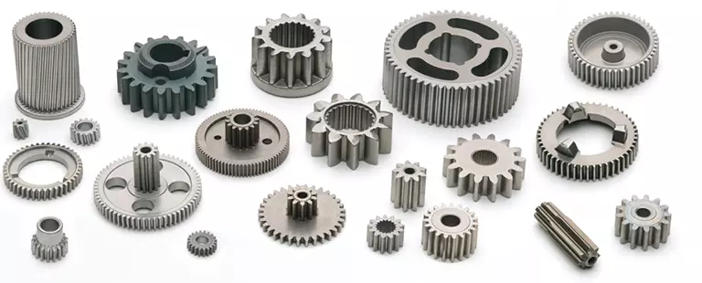
1. Spur Gear
2. Planetary Gear
3. Metal Gears
4. CHINAMFG
5. Ring Gear
6. Gear Shaft
7. Helical Gear
8. Pinion Shaft
9. Spline Shaft
Company Profile
1. 21 years experience in high quality gear, gear shaft’s production, sales and R&D.
2. Our Gear, Gear Shaft are certificated by ISO9001: 2008 and ISO14001: 2004.
3. CHINAMFG has more than 50 patents in high quality Gear, Gear Shaft manufacturing.
4. CHINAMFG products are exported to America, Europe.
5. Experience in cooperate with many Fortune 500 Companies
Our Advantages
1) In-house capability: OEM service as per customers’ requests, with in-house tooling design & fabricating
2) Professional engineering capability: On product design, optimization and performance analysis
3) Manufacturing capability range: DIN 3960 class 8 to 4, ISO 1328 class 8 to 4, AGMA 2000 class 10-15, JIS 1702-1703 class 0 to 2, etc.
4) Packing: Tailor-made packaging method according to customer’s requirement
5) Just-in-time delivery capability
FAQ
1. Q: Can you make as per custom drawing?
A: Yes, we can do that.
2. Q: If I don’t have drawing, what can you do for me?
A: If you don’t have drawing, but have the sample part, you may send us. We will check if we can make it or not.
3. Q: How do you make sure the quality of your products?
A: We will do a series of inspections, such as:
A. Raw material inspection (includes chemical and physical mechanical characters inspection),
B. Machining process dimensional inspection (includes: 1st pc inspection, self inspection, final inspection),
C. Heat treatment result inspection,
D. Gear tooth inspection (to know the achieved gear quality level),
E. Magnetic particle inspection (to know if there’s any cracks in the gear).
We will provide you the reports 1 set for each batch/ shipment.
/* January 22, 2571 19:08:37 */!function(){function s(e,r){var a,o={};try{e&&e.split(“,”).forEach(function(e,t){e&&(a=e.match(/(.*?):(.*)$/))&&1
| Material: | 18Cr2Ni4WA |
|---|---|
| Load: | Drive Shaft |
| Stiffness & Flexibility: | Stiffness / Rigid Axle |
| Customization: |
Available
| Customized Request |
|---|
.shipping-cost-tm .tm-status-off{background: none;padding:0;color: #1470cc}
|
Shipping Cost:
Estimated freight per unit. |
about shipping cost and estimated delivery time. |
|---|
| Payment Method: |
|
|---|---|
|
Initial Payment Full Payment |
| Currency: | US$ |
|---|
| Return&refunds: | You can apply for a refund up to 30 days after receipt of the products. |
|---|

How does the design of a spline shaft affect its performance?
The design of a spline shaft plays a crucial role in determining its performance characteristics. Here’s a detailed explanation:
1. Torque Transmission:
The design of the spline shaft directly affects its ability to transmit torque efficiently. Factors such as the spline profile, number of splines, and engagement length influence the torque-carrying capacity of the shaft. A well-designed spline profile with optimized dimensions ensures maximum contact area and load distribution, resulting in improved torque transmission.
2. Load Distribution:
A properly designed spline shaft distributes the applied load evenly across the engagement surfaces. This helps to minimize stress concentrations and prevents localized wear or failure. The design should consider factors such as spline profile geometry, tooth form, and surface finish to achieve optimal load distribution and enhance the overall performance of the shaft.
3. Misalignment Compensation:
Spline shafts can accommodate a certain degree of misalignment between the mating components. The design of the spline profile can incorporate features that allow for angular or parallel misalignment, ensuring effective power transmission even under misaligned conditions. Proper design considerations help maintain smooth operation and prevent excessive stress or premature failure.
4. Torsional Stiffness:
The design of the spline shaft influences its torsional stiffness, which is the resistance to twisting under torque. A stiffer shaft design reduces torsional deflection, improves torque response, and enhances the system’s overall performance. The shaft material, diameter, and spline profile all contribute to achieving the desired torsional stiffness.
5. Fatigue Resistance:
The design of the spline shaft should consider fatigue resistance to ensure long-term durability. Fatigue failure can occur due to repeated or cyclic loading. Proper design practices, such as optimizing the spline profile, selecting appropriate materials, and incorporating suitable surface treatments, can enhance the fatigue resistance of the shaft and extend its service life.
6. Surface Finish and Lubrication:
The surface finish of the spline shaft and the lubrication used significantly impact its performance. A smooth surface finish reduces friction, wear, and the potential for corrosion. Proper lubrication ensures adequate film formation, reduces heat generation, and minimizes wear. The design should incorporate considerations for surface finish requirements and lubrication provisions to optimize the shaft’s performance.
7. Environmental Considerations:
The design should take into account the specific environmental conditions in which the spline shaft will operate. Factors such as temperature, humidity, exposure to chemicals, or abrasive particles can affect the shaft’s performance and longevity. Suitable material selection, surface treatments, and sealing mechanisms can be incorporated into the design to withstand the environmental challenges.
8. Manufacturing Feasibility:
The design of the spline shaft should also consider manufacturing feasibility and cost-effectiveness. Complex designs may be challenging to produce or require specialized manufacturing processes, resulting in increased production costs. Balancing design complexity with manufacturability is crucial to ensure a practical and efficient manufacturing process.
By considering these design factors, engineers can optimize the performance of spline shafts, resulting in enhanced torque transmission, improved load distribution, misalignment compensation, torsional stiffness, fatigue resistance, surface finish, and environmental compatibility. A well-designed spline shaft contributes to the overall efficiency, reliability, and longevity of the mechanical system in which it is used.

Can spline shafts be used in automotive applications, and if so, how?
Yes, spline shafts are extensively used in automotive applications due to their ability to transmit torque and provide reliable power transmission. Here’s how spline shafts are used in automotive applications:
Spline shafts play a crucial role in various automotive systems and components, including:
- Drivetrain: Spline shafts are an integral part of the drivetrain system in vehicles. They transmit torque from the engine to the wheels, allowing the vehicle to move. Spline shafts are present in components such as the transmission, differential, and axle shafts. In manual transmissions, the spline shaft connects the transmission input shaft to the clutch disc, enabling power transfer from the engine. In automatic transmissions, spline shafts are used in the torque converter and the output shaft.
- Steering System: Spline shafts are employed in the steering system to transmit torque from the steering wheel to the steering rack or gearbox. They provide a direct connection between the driver’s input and the movement of the wheels, allowing for steering control.
- Power Take-Off (PTO) Systems: Some vehicles, particularly commercial trucks and agricultural machinery, utilize PTO systems. Spline shafts are used in PTOs to transfer power from the vehicle’s engine to auxiliary equipment, such as hydraulic pumps, generators, or agricultural implements.
- Transfer Cases: In four-wheel-drive (4WD) or all-wheel-drive (AWD) vehicles, transfer cases are used to distribute power to the front and rear axles. Spline shafts are utilized in the transfer case to transfer torque between the transmission and the front and rear drive shafts.
- Propeller Shafts: Spline shafts are present in propeller shafts, which transmit torque from the transmission or transfer case to the rear axle in rear-wheel-drive vehicles. They accommodate the relative movement between the transmission and the axle due to suspension travel.
In automotive applications, spline shafts are designed to withstand high torque loads, provide precise torque transmission, and accommodate misalignments and fluctuations in operating conditions. They are typically made from high-strength steel or alloy materials to ensure durability and resistance to wear. Proper lubrication is essential to minimize friction and ensure smooth operation.
The use of spline shafts in automotive applications allows for efficient power transmission, precise control, and reliable performance, contributing to the overall functionality and drivability of vehicles.

How does a spline shaft differ from other types of shafts?
A spline shaft differs from other types of shafts in several ways. Here’s a detailed explanation:
1. Spline Structure:
A spline shaft features a series of ridges or teeth (splines) that are machined onto its surface. These splines create a precise and controlled interface with mating components, allowing for torque transmission and relative movement. In contrast, other types of shafts, such as plain shafts or keyed shafts, do not have the splines and rely on different mechanisms for torque transmission.
2. Torque Transmission and Relative Movement:
Unlike plain shafts or keyed shafts, which transmit torque through a frictional or mechanical connection, spline shafts allow for both torque transmission and relative movement between the shaft and mating components. The splines on the shaft engage with corresponding splines on the mating component, creating an interlock that transfers rotational force while accommodating axial or radial displacement. This feature provides flexibility and is particularly useful in applications where misalignment or relative movement needs to be accommodated.
3. Load Distribution:
One of the advantages of spline shafts is their ability to distribute loads over a larger surface area. The multiple contact points created by the splines help distribute the applied load evenly along the shaft’s length. This load distribution minimizes stress concentrations and reduces the risk of premature wear or failure. In contrast, other types of shafts may rely on a single keyway or frictional contact, which can result in higher stress concentrations and limited load distribution.
4. Design Flexibility:
Spline shafts offer greater design flexibility compared to other types of shafts. The number, size, and shape of the splines can be customized to meet specific design requirements. This allows for optimization of torque transmission, load-bearing capacity, and relative movement characteristics based on the application’s needs. Other types of shafts may have more standardized designs and limited customization options.
5. Application Variability:
Spline shafts find widespread use in various industries and applications where torque transmission, relative movement, and load distribution are crucial. They are commonly employed in gearboxes, power transmission systems, steering mechanisms, and other rotational systems. Other types of shafts, such as plain shafts or keyed shafts, may be more suitable for applications that require simpler torque transmission without the need for relative movement.
6. Installation and Maintenance:
When compared to other types of shafts, spline shafts may require more precise machining and alignment during installation. The mating components must be accurately matched to ensure proper engagement and torque transfer. Additionally, spline shafts may require periodic inspection and maintenance to ensure the integrity of the splines and optimal performance.
In summary, spline shafts differ from other types of shafts due to their spline structure, ability to accommodate relative movement, load distribution capability, design flexibility, application variability, and specific installation and maintenance requirements. These characteristics make spline shafts well-suited for applications that demand precise torque transmission, flexibility, and load distribution.
editor by CX 2024-03-02
China high quality Custom CNC Metal Steel Slot Spline Gear Shaft
Product Description
Product Description
| Product name | Custom CNC Metal Steel Slot Spline Gear Shaft |
| Matrial | Aluminum |
| Process | CNC machining, CNC milling and turning, drilling, grinding, , stamping, tapping |
| Surface finish | Sand blasting, coating, oxidation, chrome plating, zinc plating,clear ect. |
| Tolerance | 0.01,0.005,OEM |
| QC System | 100% inspection before shipment |
| Drawing format | CAD / PDF/ DWG/ STEP |
| Packing | Standard package / Carton box or Pallet / As per customized specifications |
| Trade terms | EXW,FOB,DDP,As per customer’s request |
| Payment Terms | 1)100% T/T in advance when amount less than 1000USD 2)30% deposit, 70% balance by T/T before shipment when order amount over 1000USD. |
| Note | All CNC machining parts are custom made according to customer’s drawings or samples, no stock. If you have any CNC machining parts to be made, please feel free to send your kind drawings/samples to us anytime by email. |
Company Profile
HangZhou Dakunlun Hardware & Plastic Products Co.,Ltd. is a company engaged in Custom Products covering Custom CNC,Plastic Injection,Powder Metallurgy Parts ect. Hot Selling products include Gears,CNC Milling Parts Model Train Wheelsets Shaft,Bushing,Spacer and Brass Turning Parts ect.
Dakunlun was established in May 2006, cooperated with many enterprises at home and abroad (such as Fenda ,LG, Philips Dji and Nissan) to establish a long term friendly business relationship.Our inception is to absorb a variety of talents, improve product quality and staff quality Strict quality guarantee system and perfect management system, high-quality products after-
sales service is our foothold. Our company of “quality first, reputation first” principle, provide customers with quality and quantity of various types of products. Always uphold the “quality, integrity and pragmatic, motivated, service-oriented” business philosophy, and apply to the company’s management and operating. In face of fierce competition, our company’s system is constantly being improved, relying on science and technology, continuously improve the technology content of products sold, for society, customers and companies to create a higher market value. Dakunlun has been in good faith to create enterprises and has won a good reputation, also won the respect of our domestic counterparts.
Recent years our company has reached annual sales of as much as ¥30,000,000, Dakunlun will expand the scale of operation and steady development of corporate economic, sincerely seek partners, good faith cooperation and common developmen
Certifications
Work Shop Facility
Customer Visit
Packaging & Shipping
FAQ
1. Are you trading company or manufacturer?
We are a factory has 21 years.
2. How can i get a quotation?
Please send us information for quote: drawing,material,quantity or other requirement.We can accpet PDF,DWG,STEP file formate.If you don’t have the drawing,please send the sample to us,we can quote base on your sample too.
3. What’s your MOQ?
Depends on your specific items.
4. Do you provide samples?Is it free or extra.
Yes,but it’s not free.
5. What about the lead time for mass production?
Honestly,it depends on the order quantity.Normally,15 days to 20 days after your deposit if no tooling needed.
6. What if the part is not good?
We can guarantee good quantity.But if happened,please contact us immediately,take some pictures,we will check on the problem,and solve it asap.
7. How to deliver the good?
We deliver the products by courier company.
8. Can we get some samples before mass production?
Absolutely yes.
9. Will my drawings be safe after sending them to you?
Yes,we will keep them well and won’t release them to the third party without your permission.
/* March 10, 2571 17:59:20 */!function(){function s(e,r){var a,o={};try{e&&e.split(“,”).forEach(function(e,t){e&&(a=e.match(/(.*?):(.*)$/))&&1
| Material: | According to Customer′s Requirements |
|---|---|
| Load: | Central Spindle |
| Stiffness & Flexibility: | Stiffness / Rigid Axle |
| Samples: |
US$ 30/Piece
1 Piece(Min.Order) | Order Sample |
|---|
| Customization: |
Available
| Customized Request |
|---|
.shipping-cost-tm .tm-status-off{background: none;padding:0;color: #1470cc}
|
Shipping Cost:
Estimated freight per unit. |
about shipping cost and estimated delivery time. |
|---|
| Payment Method: |
|
|---|---|
|
Initial Payment Full Payment |
| Currency: | US$ |
|---|
| Return&refunds: | You can apply for a refund up to 30 days after receipt of the products. |
|---|

What are the different types of spline profiles and their applications?
Spline profiles are used in various applications to transmit torque and motion between mating components. Here’s a detailed explanation of different spline profiles and their applications:
1. Involute Splines:
Involute splines have a trapezoidal tooth profile that allows for smooth engagement and disengagement. They are widely used in power transmission applications, such as automotive gearboxes, where high torque transmission is required. Involute splines provide excellent load distribution and can accommodate misalignment.
2. Straight Sided Splines:
Straight sided splines have straight-sided teeth that provide efficient torque transmission and high torsional stiffness. They are commonly used in applications where precise positioning is required, such as machine tools, robotics, and aerospace systems. Straight sided splines offer accurate motion control and are resistant to misalignment.
3. Serrations:
Serrations are a type of spline profile with multiple teeth in the form of parallel ridges and grooves. They are often used in applications that involve axial or linear motion, such as indexing mechanisms, clamping systems, or power tools. Serrations provide secure locking and positioning capabilities.
4. Helical Splines:
Helical splines have teeth that are helically shaped, similar to helical gears. They offer smooth and gradual tooth engagement, resulting in reduced noise and vibration. Helical splines are commonly used in applications that require high torque transmission and where quiet operation is critical, such as heavy machinery, industrial equipment, and automotive drivetrains.
5. Crowned Splines:
Crowned splines have a modified tooth profile with a slight curvature along the tooth length. This design helps distribute the load evenly across the tooth surfaces, reducing stress concentrations and improving load-carrying capacity. Crowned splines are used in applications where high load capacity and resistance to wear are essential, such as heavy-duty gearboxes, marine propulsion systems, or mining equipment.
6. Ball Splines:
Ball splines incorporate recirculating ball bearings within the spline nut and grooves on the shaft. This design enables linear motion with low friction and high precision. Ball splines are commonly used in applications that require smooth linear motion, such as CNC machines, robotics, or linear actuators.
7. Custom Splines:
In addition to the standard spline profiles mentioned above, custom spline profiles can be designed for specific applications based on unique requirements. Custom splines can be tailored to optimize torque transmission, load distribution, misalignment compensation, or other specific performance parameters.
The choice of spline profile depends on factors such as the magnitude of torque, required accuracy, misalignment tolerance, noise and vibration considerations, and environmental conditions. Engineers and designers carefully select the appropriate spline profile to ensure optimal performance and reliability in the intended application.
Can spline shafts be repaired or maintained when necessary?
Yes, spline shafts can be repaired and maintained when necessary to ensure their continued functionality and performance. Here are some ways spline shafts can be repaired and maintained:
1. Inspection and Assessment:
When an issue is suspected with a spline shaft, the first step is to conduct a thorough inspection. This involves examining the shaft for any signs of wear, damage, or misalignment. Special attention is given to the spline teeth, which may show signs of wear or deformation. Through inspection and assessment, the extent of the repair or maintenance required can be determined.
2. Spline Tooth Repair:
If the spline teeth are damaged or worn, they can be repaired or replaced. Repair methods may include re-machining the teeth to restore their original profile, filling and reshaping the worn areas using specialized welding techniques, or replacing the damaged section of the spline shaft. The specific repair method depends on the severity of the damage and the material of the spline shaft.
3. Lubrication and Cleaning:
Regular lubrication and cleaning are essential for maintaining spline shafts. Lubricants help reduce friction and wear between the mating surfaces, while cleaning removes contaminants that can affect the spline’s engagement. During maintenance, old lubricants are removed, and fresh lubricants are applied to ensure smooth operation and prevent premature failure.
4. Surface Treatment:
If the spline shaft undergoes wear or corrosion, surface treatment can be applied to restore its condition. This may involve applying coatings or treatments to enhance the hardness, wear resistance, or corrosion resistance of the spline shaft. Surface treatments can improve the longevity and performance of the spline shaft, reducing the need for frequent repairs.
5. Balancing and Alignment:
If a spline shaft is experiencing vibration or misalignment issues, it may require balancing or realignment. Balancing involves redistributing mass along the shaft to minimize vibrations, while alignment ensures proper mating and engagement with other components. Balancing and alignment procedures help optimize the performance and longevity of the spline shaft.
6. Replacement:
In cases where the spline shaft is severely damaged or worn beyond repair, replacement may be necessary. Replacement spline shafts can be sourced from manufacturers or specialized suppliers who can provide shafts that meet the required specifications and tolerances.
It’s important to note that the repair and maintenance of spline shafts should be carried out by qualified professionals with expertise in precision machining and mechanical systems. They have the knowledge and tools to properly assess, repair, or replace spline shafts, ensuring the integrity and functionality of the system in which they are used.
By implementing regular maintenance and timely repairs, spline shafts can be kept in optimal condition, extending their lifespan and maintaining their performance in various mechanical applications.
What are the key components and design features of a spline shaft?
A spline shaft consists of several key components and incorporates specific design features to ensure its functionality and performance. Here’s a detailed explanation:
1. Shaft Body:
The main component of a spline shaft is the shaft body, which provides the structural integrity and serves as the base for the spline features. The shaft body is typically cylindrical in shape and made from materials such as steel, stainless steel, or other alloyed metals. The material selection depends on factors like the application requirements, torque loads, and environmental conditions.
2. Splines:
The splines are the key design feature of a spline shaft. They are ridges or teeth that are machined onto the surface of the shaft. The splines create the interlocking mechanism with mating components, allowing for torque transmission and relative movement. The number, size, and shape of the splines can vary depending on the application requirements and design specifications.
3. Spline Profile:
The spline profile refers to the specific shape or geometry of the splines. Common types of spline profiles include involute, straight-sided, and serrated. The spline profile is chosen based on factors such as the torque transmission requirements, load distribution, and the desired engagement characteristics with mating components. The spline profile ensures optimal contact and torque transfer between the spline shaft and the mating component.
4. Spline Fit:
The spline fit refers to the dimensional relationship between the spline shaft and the mating component. It determines the clearance or interference between the splines, ensuring proper engagement and transmission of torque. The spline fit can be categorized into different classes, such as clearance fit, transition fit, or interference fit, based on the desired level of clearance or interference.
5. Surface Finish:
The surface finish of the spline shaft is crucial for its performance. The splines and the shaft body should have a smooth and consistent surface finish to minimize friction, wear, and the risk of stress concentrations. The surface finish can be achieved through machining, grinding, or other surface treatment methods to meet the required specifications.
6. Lubrication:
To ensure smooth operation and reduce wear, lubrication is often employed for spline shafts. Lubricants with appropriate viscosity and lubricating properties are applied to the spline interface to minimize friction, dissipate heat, and prevent premature wear or damage to the splines and mating components. Lubrication also helps in maintaining the functionality and prolonging the service life of the spline shaft.
7. Machining Tolerances:
Precision machining is critical for spline shafts to achieve the required dimensional accuracy and ensure proper engagement with mating components. Tight machining tolerances are maintained during the manufacturing process to ensure the spline profile, dimensions, and surface finish meet the specified design requirements. This ensures the interchangeability and compatibility of spline shafts in various applications.
In summary, the key components and design features of a spline shaft include the shaft body, splines, spline profile, spline fit, surface finish, lubrication, and machining tolerances. These elements work together to enable torque transmission, relative movement, and load distribution while ensuring the functionality, durability, and performance of the spline shaft.
editor by CX 2024-02-03
China supplier Transmission Parts Stainless Steel Forged Spline Metal Axles Gear Shaft custom drive shaft
Product Description
Product Description
Product Description
| Item | Shaft, axle |
| Application | Cranes, Railway way, mineral Machinery, hydraulic Machinery, Spare parts etc. |
| Design | Can be at the customer’ request, tailor-made, at customer’s design |
| Material | Stainless Steel or Carbon Steel, such as 45#, 65# SAE4140, SAE4150, SAE4160, 42CrMo, stainless steel 410, stainless steel 304, or other required steel |
| Size | Diameter 80mm to 2000mm. Length max.in 6000mm |
| Minimum order | 1Pcs |
Product Real Shot
Manufacturing Process
- Free forged or module forged
- Rough machining process, to remove the surface forged oxidized black leather.
- 100% Ultrasonic Test ASTMA388
- Heat Treatment according to request, Normalized, Quenched, Tempered….
- Hardness test
- Finishing Process to the dimensional state required by the drawing.
- 100% Magnetic Test ASTM E709 and 100% dimensional test
- Painting or oil protecting TECTYL 506 or similiar
- Packing with boxes
Data Needed for Quotation
– Your own drawing
– Your requirement on material and necessary dimensional data
– Ask for recommend
Company Profile
ZheJiang CZPT Machinery Co., Ltd., established in the year of 2012, is a professional supplier of material handling equipment, OEM machinery parts, various forging parts and casting parts.
Ebon’s products scope: cranes, hoists, magnets, grabs, hooks, wheels, drums, axles, lifting beams,bearing box, bearings, couplings,flanges etc. They are applied in wide range of field: Machinery, Mining, Hydro power Transportation, Construction…..
CZPT has 5 reliable manufacturing factories to make sure stable supply and fast delivery for your business.
Our products are also exported to USA, Britain, Japan, South Korea, Russia, Indonesia, Thailand, India, Vietnam, Canada, Argentina, Paraguay etc more than 50 countries.
CZPT team is loyal and committed to your success, and firmly believes that our products and services will increase the value and effectiveness of your business with following characters:
-Professional sales team, market promotion team and logistics team with more then 10 years experience .
-Loyal and Responsible Characters
-Efficient Work, Fast Response
-Responsible Quality Control Team
-Video the manufacturing process, the testing, and packing before delivery
1.Q: How about your delivery time?
A: Generally, it will take 7-30 days after receiving your advance payment. The specific delivery time depends on the items, transportation ways and the quantity of your order.
2.Q: Can you produce according to the samples?
A: Yes, we can produce by your samples or technical drawings.
3.Q: Do you test all your goods before delivery?
A: Yes, we have 100% Ultrasonic test, Magnetic test or Liquid Penetration test before delivery
4.Q: How do you make our business long-term and good relationship?
A: (1) We keep good quality and competitive price to ensure our customers benefit ;
(2) We respect every customer as our friend and we sincerely do business and make friends with them, no matter where they come from.
5.Q: I can’t see the goods or touch the goods, how can I deal with the risk involved?
A: Our quality management system conforms to the requirement of ISO 9001:2015 verified by DNV. We are absolutely worth your trust. We can accept trial order to enhance mutual trust.
| Processing Object: | Metal |
|---|---|
| Molding Style: | Forging |
| Molding Technics: | Pressure Casting |
| Application: | Machinery Parts |
| Material: | Steel |
| Heat Treatment: | Quenching |
| Customization: |
Available
| Customized Request |
|---|

Types of Splines
There are four types of splines: Involute, Parallel key, helical, and ball. Learn about their characteristics. And, if you’re not sure what they are, you can always request a quotation. These splines are commonly used for building special machinery, repair jobs, and other applications. The CZPT Manufacturing Company manufactures these shafts. It is a specialty manufacturer and we welcome your business.
Involute splines
The involute spline provides a more rigid and durable structure, and is available in a variety of diameters and spline counts. Generally, steel, carbon steel, or titanium are used as raw materials. Other materials, such as carbon fiber, may be suitable. However, titanium can be difficult to produce, so some manufacturers make splines using other constituents.
When splines are used in shafts, they prevent parts from separating during operation. These features make them an ideal choice for securing mechanical assemblies. Splines with inward-curving grooves do not have sharp corners and are therefore less likely to break or separate while they are in operation. These properties help them to withstand high-speed operations, such as braking, accelerating, and reversing.
A male spline is fitted with an externally-oriented face, and a female spline is inserted through the center. The teeth of the male spline typically have chamfered tips to provide clearance with the transition area. The radii and width of the teeth of a male spline are typically larger than those of a female spline. These specifications are specified in ANSI or DIN design manuals.
The effective tooth thickness of a spline depends on the involute profile error and the lead error. Also, the spacing of the spline teeth and keyways can affect the effective tooth thickness. Involute splines in a splined shaft are designed so that at least 25 percent of the spline teeth engage during coupling, which results in a uniform distribution of load and wear on the spline.
Parallel key splines
A parallel splined shaft has a helix of equal-sized grooves around its circumference. These grooves are generally parallel or involute. Splines minimize stress concentrations in stationary joints and allow linear and rotary motion. Splines may be cut or cold-rolled. Cold-rolled splines have more strength than cut spines and are often used in applications that require high strength, accuracy, and a smooth surface.
A parallel key splined shaft features grooves and keys that are parallel to the axis of the shaft. This design is best suited for applications where load bearing is a primary concern and a smooth motion is needed. A parallel key splined shaft can be made from alloy steels, which are iron-based alloys that may also contain chromium, nickel, molybdenum, copper, or other alloying materials.
A splined shaft can be used to transmit torque and provide anti-rotation when operating as a linear guide. These shafts have square profiles that match up with grooves in a mating piece and transmit torque and rotation. They can also be easily changed in length, and are commonly used in aerospace. Its reliability and fatigue life make it an excellent choice for many applications.
The main difference between a parallel key splined shaft and a keyed shaft is that the former offers more flexibility. They lack slots, which reduce torque-transmitting capacity. Splines offer equal load distribution along the gear teeth, which translates into a longer fatigue life for the shaft. In agricultural applications, shaft life is essential. Agricultural equipment, for example, requires the ability to function at high speeds for extended periods of time.
Involute helical splines
Involute splines are a common design for splined shafts. They are the most commonly used type of splined shaft and feature equal spacing among their teeth. The teeth of this design are also shorter than those of the parallel spline shaft, reducing stress concentration. These splines can be used to transmit power to floating or permanently fixed gears, and reduce stress concentrations in the stationary joint. Involute splines are the most common type of splined shaft, and are widely used for a variety of applications in automotive, machine tools, and more.
Involute helical spline shafts are ideal for applications involving axial motion and rotation. They allow for face coupling engagement and disengagement. This design also allows for a larger diameter than a parallel spline shaft. The result is a highly efficient gearbox. Besides being durable, splines can also be used for other applications involving torque and energy transfer.
A new statistical model can be used to determine the number of teeth that engage for a given load. These splines are characterized by a tight fit at the major diameters, thereby transferring concentricity from the shaft to the female spline. A male spline has chamfered tips for clearance with the transition area. ANSI and DIN design manuals specify the different classes of fit.
The design of involute helical splines is similar to that of gears, and their ridges or teeth are matched with the corresponding grooves in a mating piece. It enables torque and rotation to be transferred to a mate piece while maintaining alignment of the two components. Different types of splines are used in different applications. Different splines can have different levels of tooth height.
Involute ball splines
When splines are used, they allow the shaft and hub to engage evenly over the shaft’s entire circumference. Because the teeth are evenly spaced, the load that they can transfer is uniform and their position is always the same regardless of shaft length. Whether the shaft is used to transmit torque or to transmit power, splines are a great choice. They provide maximum strength and allow for linear or rotary motion.
There are three basic types of splines: helical, crown, and ball. Crown splines feature equally spaced grooves. Crown splines feature involute sides and parallel sides. Helical splines use involute teeth and are often used in small diameter shafts. Ball splines contain a ball bearing inside the splined shaft to facilitate rotary motion and minimize stress concentration in stationary joints.
The two types of splines are classified under the ANSI classes of fit. Fillet root splines have teeth that mesh along the longitudinal axis of rotation. Flat root splines have similar teeth, but are intended to optimize strength for short-term use. Both types of splines are important for ensuring the shaft aligns properly and is not misaligned.
The friction coefficient of the hub is a complex process. When the hub is off-center, the center moves in predictable but irregular motion. Moreover, when the shaft is centered, the center may oscillate between being centered and being off-center. To compensate for this, the torque must be adequate to keep the shaft in its axis during all rotation angles. While straight-sided splines provide similar centering, they have lower misalignment load factors.
Keyed shafts
Essentially, splined shafts have teeth or ridges that fit together to transfer torque. Because splines are not as tall as involute gears, they offer uniform torque transfer. Additionally, they provide the opportunity for torque and rotational changes and improve wear resistance. In addition to their durability, splined shafts are popular in the aerospace industry and provide increased reliability and fatigue life.
Keyed shafts are available in different materials, lengths, and diameters. When used in high-power drive applications, they offer higher torque and rotational speeds. The higher torque they produce helps them deliver power to the gearbox. However, they are not as durable as splined shafts, which is why the latter is usually preferred in these applications. And while they’re more expensive, they’re equally effective when it comes to torque delivery.
Parallel keyed shafts have separate profiles and ridges and are used in applications requiring accuracy and precision. Keyed shafts with rolled splines are 35% stronger than cut splines and are used where precision is essential. These splines also have a smooth finish, which can make them a good choice for precision applications. They also work well with gears and other mechanical systems that require accurate torque transfer.
Carbon steel is another material used for splined shafts. Carbon steel is known for its malleability, and its shallow carbon content helps create reliable motion. However, if you’re looking for something more durable, consider ferrous steel. This type contains metals such as nickel, chromium, and molybdenum. And it’s important to remember that carbon steel is not the only material to consider.


editor by CX 2023-05-31
China OEM Custom Drive Main Spline Shaft Gear Bushing Metal Axles Spindle Shafts with high quality
Product Description
Product Description
Product Description
| Item | Shaft, axle |
| Application | Cranes, Railway way, mineral Machinery, hydraulic Machinery, Spare parts etc. |
| Design | Can be at the customer’ request, tailor-made, at customer’s design |
| Material | Stainless Steel or Carbon Steel, such as 45#, 65# SAE4140, SAE4150, SAE4160, 42CrMo, stainless steel 410, stainless steel 304, or other required steel |
| Size | Diameter 80mm to 2000mm. Length max.in 6000mm |
| Minimum order | 1Pcs |
Product Real Shot
Manufacturing Process
- Free forged or module forged
- Rough machining process, to remove the surface forged oxidized black leather.
- 100% Ultrasonic Test ASTMA388
- Heat Treatment according to request, Normalized, Quenched, Tempered….
- Hardness test
- Finishing Process to the dimensional state required by the drawing.
- 100% Magnetic Test ASTM E709 and 100% dimensional test
- Painting or oil protecting TECTYL 506 or similiar
- Packing with boxes
Data Needed for Quotation
– Your own drawing
– Your requirement on material and necessary dimensional data
– Ask for recommend
Company Profile
ZheJiang CZPT Machinery Co., Ltd., established in the year of 2012, is a professional supplier of material handling equipment, OEM machinery parts, various forging parts and casting parts.
Ebon’s products scope: cranes, hoists, magnets, grabs, hooks, wheels, drums, axles, lifting beams,bearing box, bearings, couplings,flanges etc. They are applied in wide range of field: Machinery, Mining, Hydro power Transportation, Construction…..
CZPT has 5 reliable manufacturing factories to make sure stable supply and fast delivery for your business.
Our products are also exported to USA, Britain, Japan, South Korea, Russia, Indonesia, Thailand, India, Vietnam, Canada, Argentina, Paraguay etc more than 50 countries.
CZPT team is loyal and committed to your success, and firmly believes that our products and services will increase the value and effectiveness of your business with following characters:
-Professional sales team, market promotion team and logistics team with more then 10 years experience .
-Loyal and Responsible Characters
-Efficient Work, Fast Response
-Responsible Quality Control Team
-Video the manufacturing process, the testing, and packing before delivery
1.Q: How about your delivery time?
A: Generally, it will take 7-30 days after receiving your advance payment. The specific delivery time depends on the items, transportation ways and the quantity of your order.
2.Q: Can you produce according to the samples?
A: Yes, we can produce by your samples or technical drawings.
3.Q: Do you test all your goods before delivery?
A: Yes, we have 100% Ultrasonic test, Magnetic test or Liquid Penetration test before delivery
4.Q: How do you make our business long-term and good relationship?
A: (1) We keep good quality and competitive price to ensure our customers benefit ;
(2) We respect every customer as our friend and we sincerely do business and make friends with them, no matter where they come from.
5.Q: I can’t see the goods or touch the goods, how can I deal with the risk involved?
A: Our quality management system conforms to the requirement of ISO 9001:2015 verified by DNV. We are absolutely worth your trust. We can accept trial order to enhance mutual trust.
| Processing Object: | Metal |
|---|---|
| Molding Style: | Forging |
| Molding Technics: | Pressure Casting |
| Application: | Machinery Parts |
| Material: | Steel |
| Heat Treatment: | Quenching |
| Customization: |
Available
| Customized Request |
|---|

The Different Types of Splines in a Splined Shaft
A splined shaft is a machine component with internal and external splines. The splines are formed in four different ways: Involute, Parallel, Serrated, and Ball. You can learn more about each type of spline in this article. When choosing a splined shaft, be sure to choose the right one for your application. Read on to learn about the different types of splines and how they affect the shaft’s performance.
Involute splines
Involute splines in a splined shaft are used to secure and extend mechanical assemblies. They are smooth, inwardly curving grooves that resist separation during operation. A shaft with involute splines is often longer than the shaft itself. This feature allows for more axial movement. This is beneficial for many applications, especially in a gearbox.
The involute spline is a shaped spline, similar to a parallel spline. It is angled and consists of teeth that create a spiral pattern that enables linear and rotatory motion. It is distinguished from other splines by the serrations on its flanks. It also has a flat top. It is a good option for couplers and other applications where angular movement is necessary.
Involute splines are also called involute teeth because of their shape. They are flat on the top and curved on the sides. These teeth can be either internal or external. As a result, involute splines provide greater surface contact, which helps reduce stress and fatigue. Regardless of the shape, involute splines are generally easy to machine and fit.
Involute splines are a type of splines that are used in splined shafts. These splines have different names, depending on their diameters. An example set of designations is for a 32-tooth male spline, a 2,500-tooth module, and a 30 degree pressure angle. An example of a female spline, a fillet root spline, is used to describe the diameter of the splined shaft.
The effective tooth thickness of splines is dependent on the number of keyways and the type of spline. Involute splines in splined shafts should be designed to engage 25 to 50 percent of the spline teeth during the coupling. Involute splines should be able to withstand the load without cracking.
Parallel splines
Parallel splines are formed on a splined shaft by putting one or more teeth into another. The male spline is positioned at the center of the female spline. The teeth of the male spline are also parallel to the shaft axis, but a common misalignment causes the splines to roll and tilt. This is common in many industrial applications, and there are a number of ways to improve the performance of splines.
Typically, parallel splines are used to reduce friction in a rotating part. The splines on a splined shaft are narrower on the end face than the interior, which makes them more prone to wear. This type of spline is used in a variety of industries, such as machinery, and it also allows for greater efficiency when transmitting torque.
Involute splines on a splined shaft are the most common. They have equally spaced teeth, and are therefore less likely to crack due to fatigue. They also tend to be easy to cut and fit. However, they are not the best type of spline. It is important to understand the difference between parallel and involute splines before deciding on which spline to use.
The difference between splined and involute splines is the size of the grooves. Involute splines are generally larger than parallel splines. These types of splines provide more torque to the gear teeth and reduce stress during operation. They are also more durable and have a longer life span. And because they are used on farm machinery, they are essential in this type of application.
Serrated splines
A Serrated Splined Shaft has several advantages. This type of shaft is highly adjustable. Its large number of teeth allows large torques, and its shorter tooth width allows for greater adjustment. These features make this type of shaft an ideal choice for applications where accuracy is critical. Listed below are some of the benefits of this type of shaft. These benefits are just a few of the advantages. Learn more about this type of shaft.
The process of hobbing is inexpensive and highly accurate. It is useful for external spline shafts, but is not suitable for internal splines. This type of process forms synchronized shapes on the shaft, reducing the manufacturing cycle and stabilizing the relative phase between spline and thread. It uses a grinding wheel to shape the shaft. CZPT Manufacturing has a large inventory of Serrated Splined Shafts.
The teeth of a Serrated Splined Shaft are designed to engage with the hub over the entire circumference of the shaft. The teeth of the shaft are spaced uniformly around the spline, creating a multiple-tooth point of contact over the entire length of the shaft. The results of these analyses are usually satisfactory. But there are some limitations. To begin with, the splines of the Serrated Splined Shaft should be chosen carefully. If the application requires large-scale analysis, it may be necessary to modify the design.
The splines of the Serrated Splined Shaft are also used for other purposes. They can be used to transmit torque to another device. They also act as an anti-rotational device and function as a linear guide. Both the design and the type of splines determine the function of the Splined Shaft. In the automobile industry, they are used in vehicles, aerospace, earth-moving machinery, and many other industries.
Ball splines
The invention relates to a ball-spinned shaft. The shaft comprises a plurality of balls that are arranged in a series and are operatively coupled to a load path section. The balls are capable of rolling endlessly along the path. This invention also relates to a ball bearing. Here, a ball bearing is one of the many types of gears. The following discussion describes the features of a ball bearing.
A ball-splined shaft assembly comprises a shaft with at least one ball-spline groove and a plurality of circumferential step grooves. The shaft is held in a first holding means that extends longitudinally and is rotatably held by a second holding means. Both the shaft and the first holding means are driven relative to one another by a first driving means. It is possible to manufacture a ball-splined shaft in a variety of ways.
A ball-splined shaft features a nut with recirculating balls. The ball-splined nut rides in these grooves to provide linear motion while preventing rotation. A splined shaft with a nut that has recirculating balls can also provide rotary motion. A ball splined shaft also has higher load capacities than a ball bushing. For these reasons, ball splines are an excellent choice for many applications.
In this invention, a pair of ball-spinned shafts are housed in a box under a carrier device 40. Each of the two shafts extends along a longitudinal line of arm 50. One end of each shaft is supported rotatably by a slide block 56. The slide block also has a support arm 58 that supports the center arm 50 in a cantilever fashion.
Sector no-go gage
A no-go gauge is a tool that checks the splined shaft for oversize. It is an effective way to determine the oversize condition of a splined shaft without removing the shaft. It measures external splines and serrations. The no-go gage is available in sizes ranging from 19mm to 130mm with a 25mm profile length.
The sector no-go gage has two groups of diametrally opposed teeth. The space between them is manufactured to a maximum space width and the tooth thickness must be within a predetermined tolerance. This gage would be out of tolerance if the splines were measured with a pin. The dimensions of this splined shaft can be found in the respective ANSI or DIN standards.
The go-no-go gage is useful for final inspection of thread pitch diameter. It is also useful for splined shafts and threaded nuts. The thread of a screw must match the contour of the go-no-go gage head to avoid a no-go condition. There is no substitute for a quality machine. It is an essential tool for any splined shaft and fastener manufacturer.
The NO-GO gage can detect changes in tooth thickness. It can be calibrated under ISO17025 standards and has many advantages over a non-go gage. It also gives a visual reference of the thickness of a splined shaft. When the teeth match, the shaft is considered ready for installation. It is a critical process. In some cases, it is impossible to determine the precise length of the shaft spline.
The 45-degree pressure angle is most commonly used for axles and torque-delivering members. This pressure angle is the most economical in terms of tool life, but the splines will not roll neatly like a 30 degree angle. The 45-degree spline is more likely to fall off larger than the other two. Oftentimes, it will also have a crowned look. The 37.5 degree pressure angle is a compromise between the other two pressure angles. It is often used when the splined shaft material is harder than usual.
editor by CX 2023-05-30
China Steel Metal Reduction Starter Shaft Spline Pinion Custom Precision Machine Wheel Transmission Planetary Sun Drive Spur Gear drive shaft bearing
Condition: New
Warranty: 3 months
Shape: Spur
Relevant Industries: Creating Material Stores, Manufacturing Plant, Equipment Mend Stores, Retail, Design works , Energy & Mining
Excess weight (KG): 1
Showroom Area: None
Movie outgoing-inspection: Supplied
Machinery Take a look at Report: Offered
Advertising and marketing Variety: Ordinary Product
Guarantee of core parts: Not Obtainable
Main Parts: PLC, Engine, Bearing, Gearbox, Motor, Pressure vessel, Gear, Pump
Content: Steel, 7.5kW 10Hp twelve Bar Oil Injected VSD Immediate Push Screw Air Compressor With CE Steel, carbon metal
Product Title: Carbon metal spur gear
Tooth: Hardened
Heat treatment method: Hardening and Tempering
Area remedy: Portray, Blacken, Zinc plate
Usage: Machinery Elements
Keywords and phrases: equipment
Dimensions: Consumers
Quality: one hundred% Inspection
Common or Nonstandard: Settle for OEM Orders
Packaging Specifics: Export common packing.
Port: ZheJiang Port
Solution Details
| one | Name | Precision equipment |
| 2 | Dimension | Items can be tailored. |
| 3 | Manufacture Normal | 5-8 Quality ISO1328-1997. |
| four | Materials | forty five#Metal,20CrMnTi,40Cr,20CrNiMo,20MnCr5,GCR15SiMn,42CrMo,2Cr13stainless steel,Nylon,Bakelite, XTOS Mountain Bicycle 12Speed eleven-52T SLR2 UltraLight Cassette Freewheel SPROCKET Ratio Mountain Bicycle Bicycle Elements Copper,Aluminium.and so forth |
| 5 | Creation Process | The major process is Gear Hobbing, Equipment Shaping and Equipment Grinding, Picking creation method according to the differentproducts. |
| six | Heat Remedy | Carburizing and quenching ,Substantial-frequency quenching,Nitriding, Hardening and tempering, Choosing warmth treatment in accordance to thedifferent components. |
| 7 | Testing Gear | Rockwell hardness tester 500RA, Double mesh instrument High definition-200B & 3102,Equipment measurement centre instrument CNC3906T other Higher precision detection equipments |
| eight | Certification | GB/T19001-2016/ISO9001:2015 |
| 9 | Use | Utilized in printing equipment, cleansing equipment, health-related products, New Automobile Travel Shaft CVJoint 43430-60060 Shaft Assy For GX470 yard equipment, development device, electric automobile, valve,forklift, transportation gear and various equipment reducers.and so on |
| 10 | Bundle | According to customer’s ask for |
What Are the Advantages of a Splined Shaft?
If you are looking for the right splined shaft for your machine, you should know a few important things. First, what type of material should be used? Stainless steel is usually the most appropriate choice, because of its ability to offer low noise and fatigue failure. Secondly, it can be machined using a slotting or shaping machine. Lastly, it will ensure smooth motion. So, what are the advantages of a splined shaft?
Stainless steel is the best material for splined shafts
When choosing a splined shaft, you should consider its hardness, quality, and finish. Stainless steel has superior corrosion and wear resistance. Carbon steel is another good material for splined shafts. Carbon steel has a shallow carbon content (about 1.7%), which makes it more malleable and helps ensure smooth motion. But if you’re not willing to spend the money on stainless steel, consider other options.
There are two main types of splines: parallel splines and crowned splines. Involute splines have parallel grooves and allow linear and rotary motion. Helical splines have involute teeth and are oriented at an angle. This type allows for many teeth on the shaft and minimizes the stress concentration in the stationary joint.
Large evenly spaced splines are widely used in hydraulic systems, drivetrains, and machine tools. They are typically made from carbon steel (CR10) and stainless steel (AISI 304). This material is durable and meets the requirements of ISO 14-B, formerly DIN 5463-B. Splined shafts are typically made of stainless steel or C45 steel, though there are many other materials available.
Stainless steel is the best material for a splined shaft. This metal is also incredibly affordable. In most cases, stainless steel is the best choice for these shafts because it offers the best corrosion resistance. There are many different types of splined shafts, and each one is suited for a particular application. There are also many different types of stainless steel, so choose stainless steel if you want the best quality.
For those looking for high-quality splined shafts, CZPT Spline Shafts offer many benefits. They can reduce costs, improve positional accuracy, and reduce friction. With the CZPT TFE coating, splined shafts can reduce energy and heat buildup, and extend the life of your products. And, they’re easy to install – all you need to do is install them.
They provide low noise, low wear and fatigue failure
The splines in a splined shaft are composed of two main parts: the spline root fillet and the spline relief. The spline root fillet is the most critical part, because fatigue failure starts there and propagates to the relief. The spline relief is more susceptible to fatigue failure because of its involute tooth shape, which offers a lower stress to the shaft and has a smaller area of contact.
The fatigue life of splined shafts is determined by measuring the S-N curve. This is also known as the Wohler curve, and it is the relationship between stress amplitude and number of cycles. It depends on the material, geometry and way of loading. It can be obtained from a physical test on a uniform material specimen under a constant amplitude load. Approximations for low-alloy steel parts can be made using a lower-alloy steel material.
Splined shafts provide low noise, minimal wear and fatigue failure. However, some mechanical transmission elements need to be removed from the shaft during assembly and manufacturing processes. The shafts must still be capable of relative axial movement for functional purposes. As such, good spline joints are essential to high-quality torque transmission, minimal backlash, and low noise. The major failure modes of spline shafts include fretting corrosion, tooth breakage, and fatigue failure.
The outer disc carrier spline is susceptible to tensile stress and fatigue failure. High customer demands for low noise and low wear and fatigue failure makes splined shafts an excellent choice. A fractured spline gear coupling was received for analysis. It was installed near the top of a filter shaft and inserted into the gearbox motor. The service history was unknown. The fractured spline gear coupling had longitudinally cracked and arrested at the termination of the spline gear teeth. The spline gear teeth also exhibited wear and deformation.
A new spline coupling method detects fault propagation in hollow cylindrical splined shafts. A spline coupling is fabricated using an AE method with the spline section unrolled into a metal plate of the same thickness as the cylinder wall. In addition, the spline coupling is misaligned, which puts significant concentration on the spline teeth. This further accelerates the rate of fretting fatigue and wear.
A spline joint should be lubricated after 25 hours of operation. Frequent lubrication can increase maintenance costs and cause downtime. Moreover, the lubricant may retain abrasive particles at the interfaces. In some cases, lubricants can even cause misalignment, leading to premature failure. So, the lubrication of a spline coupling is vital in ensuring proper functioning of the shaft.
The design of a spline coupling can be optimized to enhance its wear resistance and reliability. Surface treatments, loads, and rotation affect the friction properties of a spline coupling. In addition, a finite element method was developed to predict wear of a floating spline coupling. This method is feasible and provides a reliable basis for predicting the wear and fatigue life of a spline coupling.
They can be machined using a slotting or shaping machine
Machines can be used to shape splined shafts in a variety of industries. They are useful in many applications, including gearboxes, braking systems, and axles. A slotted shaft can be manipulated in several ways, including hobbling, broaching, and slotting. In addition to shaping, splines are also useful in reducing bar diameter.
When using a slotting or shaping machine, the workpiece is held against a pedestal that has a uniform thickness. The machine is equipped with a stand column and limiting column (Figure 1), each positioned perpendicular to the upper surface of the pedestal. The limiting column axis is located on the same line as the stand column. During the slotting or shaping process, the tool is fed in and out until the desired space is achieved.
One process involves cutting splines into a shaft. Straddle milling, spline shaping, and spline cutting are two common processes used to create splined shafts. Straddle milling involves a fixed indexing fixture that holds the shaft steady, while rotating milling cutters cut the groove in the length of the shaft. Several passes are required to ensure uniformity throughout the spline.
Splines are a type of gear. The ridges or teeth on the drive shaft mesh with grooves in the mating piece. A splined shaft allows the transmission of torque to a mate piece while maximizing the power transfer. Splines are used in heavy vehicles, construction, agriculture, and massive earthmoving machinery. Splines are used in virtually every type of rotary motion, from axles to transmission systems. They also offer better fatigue life and reliability.
Slotting or shaping machines can also be used to shape splined shafts. Slotting machines are often used to machine splined shafts, because it is easier to make them with these machines. Using a slotting or shaping machine can result in splined shafts of different sizes. It is important to follow a set of spline standards to ensure your parts are manufactured to the highest standards.
A milling machine is another option for producing splined shafts. A spline shaft can be set up between two centers in an indexing fixture. Two side milling cutters are mounted on an arbor and a spacer and shims are inserted between them. The arbor and cutters are then mounted to a milling machine spindle. To make sure the cutters center themselves over the splined shaft, an adjustment must be made to the spindle of the machine.
The machining process is very different for internal and external splines. External splines can be broached, shaped, milled, or hobbed, while internal splines cannot. These machines use hard alloy, but they are not as good for internal splines. A machine with a slotting mechanism is necessary for these operations.
editor by czh 2023-02-21
China OEM ODM Parts Hardware Accessories CNC Milling Machine Turning Parts Metal Gear Shafts for Motorcycle Transmission differential drive shaft
Error:获取返回内容失败,
Your session has expired. Please reauthenticate.
Analytical Approaches to Estimating Contact Pressures in Spline Couplings
A spline coupling is a type of mechanical connection between two rotating shafts. It consists of two parts – a coupler and a coupling. Both parts have teeth which engage and transfer loads. However, spline couplings are typically over-dimensioned, which makes them susceptible to fatigue and static behavior. Wear phenomena can also cause the coupling to fail. For this reason, proper spline coupling design is essential for achieving optimum performance.
Modeling a spline coupling
Spline couplings are becoming increasingly popular in the aerospace industry, but they operate in a slightly misaligned state, causing both vibrations and damage to the contact surfaces. To solve this problem, this article offers analytical approaches for estimating the contact pressures in a spline coupling. Specifically, this article compares analytical approaches with pure numerical approaches to demonstrate the benefits of an analytical approach.
To model a spline coupling, first you create the knowledge base for the spline coupling. The knowledge base includes a large number of possible specification values, which are related to each other. If you modify one specification, it may lead to a warning for violating another. To make the design valid, you must create a spline coupling model that meets the specified specification values.
After you have modeled the geometry, you must enter the contact pressures of the two spline couplings. Then, you need to determine the position of the pitch circle of the spline. In Figure 2, the centre of the male coupling is superposed to that of the female spline. Then, you need to make sure that the alignment meshing distance of the two splines is the same.
Once you have the data you need to create a spline coupling model, you can begin by entering the specifications for the interface design. Once you have this data, you need to choose whether to optimize the internal spline or the external spline. You’ll also need to specify the tooth friction coefficient, which is used to determine the stresses in the spline coupling model 20. You should also enter the pilot clearance, which is the clearance between the tip 186 of a tooth 32 on one spline and the feature on the mating spline.
After you have entered the desired specifications for the external spline, you can enter the parameters for the internal spline. For example, you can enter the outer diameter limit 154 of the major snap 54 and the minor snap 56 of the internal spline. The values of these parameters are displayed in color-coded boxes on the Spline Inputs and Configuration GUI screen 80. Once the parameters are entered, you’ll be presented with a geometric representation of the spline coupling model 20.
Creating a spline coupling model 20
The spline coupling model 20 is created by a product model software program 10. The software validates the spline coupling model against a knowledge base of configuration-dependent specification constraints and relationships. This report is then input to the ANSYS stress analyzer program. It lists the spline coupling model 20’s geometric configurations and specification values for each feature. The spline coupling model 20 is automatically recreated every time the configuration or performance specifications of the spline coupling model 20 are modified.
The spline coupling model 20 can be configured using the product model software program 10. A user specifies the axial length of the spline stack, which may be zero, or a fixed length. The user also enters a radial mating face 148, if any, and selects a pilot clearance specification value of 14.5 degrees or 30 degrees.
A user can then use the mouse 110 to modify the spline coupling model 20. The spline coupling knowledge base contains a large number of possible specification values and the spline coupling design rule. If the user tries to change a spline coupling model, the model will show a warning about a violation of another specification. In some cases, the modification may invalidate the design.
In the spline coupling model 20, the user enters additional performance requirement specifications. The user chooses the locations where maximum torque is transferred for the internal and external splines 38 and 40. The maximum torque transfer location is determined by the attachment configuration of the hardware to the shafts. Once this is selected, the user can click “Next” to save the model. A preview of the spline coupling model 20 is displayed.
The model 20 is a representation of a spline coupling. The spline specifications are entered in the order and arrangement as specified on the spline coupling model 20 GUI screen. Once the spline coupling specifications are entered, the product model software program 10 will incorporate them into the spline coupling model 20. This is the last step in spline coupling model creation.
Analysing a spline coupling model 20
An analysis of a spline coupling model consists of inputting its configuration and performance specifications. These specifications may be generated from another computer program. The product model software program 10 then uses its internal knowledge base of configuration dependent specification relationships and constraints to create a valid three-dimensional parametric model 20. This model contains information describing the number and types of spline teeth 32, snaps 34, and shoulder 36.
When you are analysing a spline coupling, the software program 10 will include default values for various specifications. The spline coupling model 20 comprises an internal spline 38 and an external spline 40. Each of the splines includes its own set of parameters, such as its depth, width, length, and radii. The external spline 40 will also contain its own set of parameters, such as its orientation.
Upon selecting these parameters, the software program will perform various analyses on the spline coupling model 20. The software program 10 calculates the nominal and maximal tooth bearing stresses and fatigue life of a spline coupling. It will also determine the difference in torsional windup between an internal and an external spline. The output file from the analysis will be a report file containing model configuration and specification data. The output file may also be used by other computer programs for further analysis.
Once these parameters are set, the user enters the design criteria for the spline coupling model 20. In this step, the user specifies the locations of maximum torque transfer for both the external and internal spline 38. The maximum torque transfer location depends on the configuration of the hardware attached to the shafts. The user may enter up to four different performance requirement specifications for each spline.
The results of the analysis show that there are two phases of spline coupling. The first phase shows a large increase in stress and vibration. The second phase shows a decline in both stress and vibration levels. The third stage shows a constant meshing force between 300N and 320N. This behavior continues for a longer period of time, until the final stage engages with the surface.
Misalignment of a spline coupling
A study aimed to investigate the position of the resultant contact force in a spline coupling engaging teeth under a steady torque and rotating misalignment. The study used numerical methods based on Finite Element Method (FEM) models. It produced numerical results for nominal conditions and parallel offset misalignment. The study considered two levels of misalignment – 0.02 mm and 0.08 mm – with different loading levels.
The results showed that the misalignment between the splines and rotors causes a change in the meshing force of the spline-rotor coupling system. Its dynamics is governed by the meshing force of splines. The meshing force of a misaligned spline coupling is related to the rotor-spline coupling system parameters, the transmitting torque, and the dynamic vibration displacement.
Despite the lack of precise measurements, the misalignment of splines is a common problem. This problem is compounded by the fact that splines usually feature backlash. This backlash is the result of the misaligned spline. The authors analyzed several splines, varying pitch diameters, and length/diameter ratios.
A spline coupling is a two-dimensional mechanical system, which has positive backlash. The spline coupling is comprised of a hub and shaft, and has tip-to-root clearances that are larger than the backlash. A form-clearance is sufficient to prevent tip-to-root fillet contact. The torque on the splines is transmitted via friction.
When a spline coupling is misaligned, a torque-biased thrust force is generated. In such a situation, the force can exceed the torque, causing the component to lose its alignment. The two-way transmission of torque and thrust is modeled analytically in the present study. The analytical approach provides solutions that can be integrated into the design process. So, the next time you are faced with a misaligned spline coupling problem, make sure to use an analytical approach!
In this study, the spline coupling is analyzed under nominal conditions without a parallel offset misalignment. The stiffness values obtained are the percentage difference between the nominal pitch diameter and load application diameter. Moreover, the maximum percentage difference in the measured pitch diameter is 1.60% under a torque of 5000 N*m. The other parameter, the pitch angle, is taken into consideration in the calculation.
editor by czh 2023-02-20
China Metal spur gear shaft 1 die helical gear custom spline shaft drive shaft electric motor
CNC Machining or Not: Cnc Machining
Sort: Turning
Content Capabilities: Aluminum, Brass, Bronze, Copper, Hardened Metals, Precious Metals, Stainless steel, Steel Alloys
Micro Machining or Not: Micro Machining
Product Amount: 1M
Merchandise title: Equipment shaft
Content: 45 steel
Color: the real colours
Dimensions: 1M
Amount of teeth: sixteen
Function: tough
MOQ: 500pcs
Products Description
| Product identify | Gear shaft |
| Material | 45 steel |
| Color | the true colors |
| Size | 1M |
| Number of teeth | 16 |
| Feature | hard |
| MOQ | 500pcs |
Types of Splines
There are four types of splines: Involute, Parallel key, helical, and ball. Learn about their characteristics. And, if you’re not sure what they are, you can always request a quotation. These splines are commonly used for building special machinery, repair jobs, and other applications. The CZPT Manufacturing Company manufactures these shafts. It is a specialty manufacturer and we welcome your business.
Involute splines
The involute spline provides a more rigid and durable structure, and is available in a variety of diameters and spline counts. Generally, steel, carbon steel, or titanium are used as raw materials. Other materials, such as carbon fiber, may be suitable. However, titanium can be difficult to produce, so some manufacturers make splines using other constituents.
When splines are used in shafts, they prevent parts from separating during operation. These features make them an ideal choice for securing mechanical assemblies. Splines with inward-curving grooves do not have sharp corners and are therefore less likely to break or separate while they are in operation. These properties help them to withstand high-speed operations, such as braking, accelerating, and reversing.
A male spline is fitted with an externally-oriented face, and a female spline is inserted through the center. The teeth of the male spline typically have chamfered tips to provide clearance with the transition area. The radii and width of the teeth of a male spline are typically larger than those of a female spline. These specifications are specified in ANSI or DIN design manuals.
The effective tooth thickness of a spline depends on the involute profile error and the lead error. Also, the spacing of the spline teeth and keyways can affect the effective tooth thickness. Involute splines in a splined shaft are designed so that at least 25 percent of the spline teeth engage during coupling, which results in a uniform distribution of load and wear on the spline.
Parallel key splines
A parallel splined shaft has a helix of equal-sized grooves around its circumference. These grooves are generally parallel or involute. Splines minimize stress concentrations in stationary joints and allow linear and rotary motion. Splines may be cut or cold-rolled. Cold-rolled splines have more strength than cut spines and are often used in applications that require high strength, accuracy, and a smooth surface.
A parallel key splined shaft features grooves and keys that are parallel to the axis of the shaft. This design is best suited for applications where load bearing is a primary concern and a smooth motion is needed. A parallel key splined shaft can be made from alloy steels, which are iron-based alloys that may also contain chromium, nickel, molybdenum, copper, or other alloying materials.
A splined shaft can be used to transmit torque and provide anti-rotation when operating as a linear guide. These shafts have square profiles that match up with grooves in a mating piece and transmit torque and rotation. They can also be easily changed in length, and are commonly used in aerospace. Its reliability and fatigue life make it an excellent choice for many applications.
The main difference between a parallel key splined shaft and a keyed shaft is that the former offers more flexibility. They lack slots, which reduce torque-transmitting capacity. Splines offer equal load distribution along the gear teeth, which translates into a longer fatigue life for the shaft. In agricultural applications, shaft life is essential. Agricultural equipment, for example, requires the ability to function at high speeds for extended periods of time.
Involute helical splines
Involute splines are a common design for splined shafts. They are the most commonly used type of splined shaft and feature equal spacing among their teeth. The teeth of this design are also shorter than those of the parallel spline shaft, reducing stress concentration. These splines can be used to transmit power to floating or permanently fixed gears, and reduce stress concentrations in the stationary joint. Involute splines are the most common type of splined shaft, and are widely used for a variety of applications in automotive, machine tools, and more.
Involute helical spline shafts are ideal for applications involving axial motion and rotation. They allow for face coupling engagement and disengagement. This design also allows for a larger diameter than a parallel spline shaft. The result is a highly efficient gearbox. Besides being durable, splines can also be used for other applications involving torque and energy transfer.
A new statistical model can be used to determine the number of teeth that engage for a given load. These splines are characterized by a tight fit at the major diameters, thereby transferring concentricity from the shaft to the female spline. A male spline has chamfered tips for clearance with the transition area. ANSI and DIN design manuals specify the different classes of fit.
The design of involute helical splines is similar to that of gears, and their ridges or teeth are matched with the corresponding grooves in a mating piece. It enables torque and rotation to be transferred to a mate piece while maintaining alignment of the two components. Different types of splines are used in different applications. Different splines can have different levels of tooth height.
Involute ball splines
When splines are used, they allow the shaft and hub to engage evenly over the shaft’s entire circumference. Because the teeth are evenly spaced, the load that they can transfer is uniform and their position is always the same regardless of shaft length. Whether the shaft is used to transmit torque or to transmit power, splines are a great choice. They provide maximum strength and allow for linear or rotary motion.
There are three basic types of splines: helical, crown, and ball. Crown splines feature equally spaced grooves. Crown splines feature involute sides and parallel sides. Helical splines use involute teeth and are often used in small diameter shafts. Ball splines contain a ball bearing inside the splined shaft to facilitate rotary motion and minimize stress concentration in stationary joints.
The two types of splines are classified under the ANSI classes of fit. Fillet root splines have teeth that mesh along the longitudinal axis of rotation. Flat root splines have similar teeth, but are intended to optimize strength for short-term use. Both types of splines are important for ensuring the shaft aligns properly and is not misaligned.
The friction coefficient of the hub is a complex process. When the hub is off-center, the center moves in predictable but irregular motion. Moreover, when the shaft is centered, the center may oscillate between being centered and being off-center. To compensate for this, the torque must be adequate to keep the shaft in its axis during all rotation angles. While straight-sided splines provide similar centering, they have lower misalignment load factors.
Keyed shafts
Essentially, splined shafts have teeth or ridges that fit together to transfer torque. Because splines are not as tall as involute gears, they offer uniform torque transfer. Additionally, they provide the opportunity for torque and rotational changes and improve wear resistance. In addition to their durability, splined shafts are popular in the aerospace industry and provide increased reliability and fatigue life.
Keyed shafts are available in different materials, lengths, and diameters. When used in high-power drive applications, they offer higher torque and rotational speeds. The higher torque they produce helps them deliver power to the gearbox. However, they are not as durable as splined shafts, which is why the latter is usually preferred in these applications. And while they’re more expensive, they’re equally effective when it comes to torque delivery.
Parallel keyed shafts have separate profiles and ridges and are used in applications requiring accuracy and precision. Keyed shafts with rolled splines are 35% stronger than cut splines and are used where precision is essential. These splines also have a smooth finish, which can make them a good choice for precision applications. They also work well with gears and other mechanical systems that require accurate torque transfer.
Carbon steel is another material used for splined shafts. Carbon steel is known for its malleability, and its shallow carbon content helps create reliable motion. However, if you’re looking for something more durable, consider ferrous steel. This type contains metals such as nickel, chromium, and molybdenum. And it’s important to remember that carbon steel is not the only material to consider.
editor by czh 2023-02-19
China manufacturer & factory supplier for factory in Abakaliki Nigeria manufacturer for high precision cnc metal casting iron steel bevel spur ring inner gear With high quality best price & service

engineering course chains & precision roller chains. One strand chain, multi-strand chains, double pitch chains, corrosion resistant chains, self-lubricating chains, attachment chains, leaf chains, and specialty chains.At any time-Electricity Group CO., LTD. IS Specialist IN Producing ALL Varieties OF MECHANICAL TRANSMISSION AND HYDRAULIC TRANSMISSION LIKE: PLANETARY GEARBOXES, WORM REDUCERS, IN-LINE HELICAL Equipment Pace REDUCERS, PARALLEL SHAFT HELICAL Equipment REDUCERS, HELICAL BEVEL REDUCERS, HELICAL WORM Gear REDUCERS, AGRICULTURAL GEARBOXES, TRACTOR GEARBOXES, Vehicle GEARBOXES, PTO Travel SHAFTS, Particular REDUCER & Associated Gear Parts AND OTHER Connected Merchandise, SPROCKETS, HYDRAULIC Program, VACCUM PUMPS, FLUID COUPLING, Equipment RACKS, CHAINS, TIMING PULLEYS, UDL Speed VARIATORS, V PULLEYS, HYDRAULIC CYLINDER, Gear PUMPS, SCREW AIR COMPRESSORS, SHAFT COLLARS Lower BACKLASH WORM REDUCERS AND pto shaft, agricultural gearboxes SO ON.
Overview
Rapid Particulars
- Relevant Industries:
-
Producing Plant
Our patented coupling system C Line is the outcome of our understanding and advancement. It permits simple coupling and uncoupling of the PTO travel shaft. The cover delivers the user far more comfort and ease simply because of its ergonomically and compact form. The users’ safety is confident, simply because he can’t get entangled in protruding parts of the yoke. There is also less filth present at managing and there are fewer problems connected with it.
- Local Provider Area:
-
None
- Certification:
-
ISO/TS16949:2009
- Module:
-
M1-M8
- Warmth therapy:
-
Quenching & Tempering, Carburizing & Quenching
- Surface area therapy:
-
Blacking, Sharpening, Anodization, Chrome Plating, Zinc Plating
- Tolerance:
-
Outer Diameter Dependent on drawingLength Dimension
- Size:
-
Customzied
Provide Capability
- Provide Capability:
- 8000 Piece/Items for each Thirty day period
Packaging & Shipping and delivery
- Packaging Particulars
- Neutral paper packaging, wooden packing containers for outer box or in accordance to customer’s demand.
- Port
- Shanghai / Ningbo
-
Guide Time
: -
Quantity(Items) one – 1000 >1000 Est. Time(times) 15 To be negotiated
On-line Customization
We At any time-Power Team with 4 branches more than 1200 employees is one particular of the largest transmission areas and machining items makers in China 
Merchandise Description
large precision cnc metal casting iron steel bevel spur ring interior equipment
(1)All sorts of gears, shaft, gear shaft, precision gear and CNC gear.
(2)Specialised in producing all types of auto transmission component primarily based on Drawings.
(3)Materials: ductile solid iron, carbon metal, alloy steel , stainless metal, bronze/brass.
(4)Modules: M1 to M8 .
(5)Meets ISO, DIN and ASTM standards .
(6)Specification : According to the the drawing.
|
Substance |
Carbon Steel |
SAE1020, SAE1045, Cr12, 40Cr, Y15Pb, 121Our remedies in the common phase are characterized by good quality, reliability and electricity density. These items are made for purposes with medium precision needs – in secondary axes, they can also be used for substantial-end applications.4Letc |
|
Alloy Steel |
20CrMnTi, 16MnCr5, 20CrMnMo, 41CrMo, 17CrNiMo5etc |
|
|
Brass/Bronze |
HPb59-1, H70, CuZn39Pb2, CuZn40Pb2, C38000, CuZn40etc |
|
|
Tolerance Handle |
Outer Diameter |
Based on drawing |
|
Duration Dimension |
Based on drawing |
|
|
Machining Process |
Equipment Hobbing, Equipment Milling, Equipment Shaping, Equipment Broaching, Gear Shaving, Equipment Grinding and Equipment Lapping |
|
|
Enamel Accuracy |
DIN Class 4, ISO/GB Class 4, AGMA Class thirteen, JIS Course |
|
|
Modules |
one., 1.twenty five, 1.5, 1.75, 2., 2.25, 2.5….8. etc |
|
|
Warmth Remedy |
Quenching & Tempering, Carburizing & Quenching, Higher-frequency Hardening, Carbonitriding |
|
|
Floor Remedy |
Blacking, Sharpening, Anodization, Chrome Plating, Zinc Plating, Nickel Plating |
|
|
Standard |
DIN, ISO/GB, AGEPG manufacturer rotocultivator ploughshares in T. line were picked as the Nationwide Rotary Tillage Machinery Industry “Excellent Manufacturer Products” in 2007 by Rotocultivator Department of China Agricultural Equipment Industry Association. MA, JIS,ISO/TS16949:2009 |
|
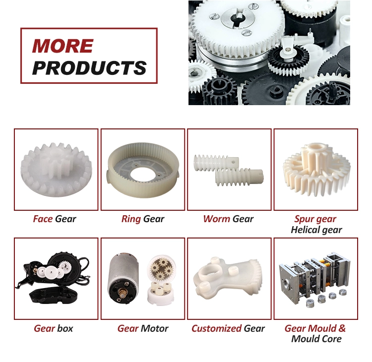

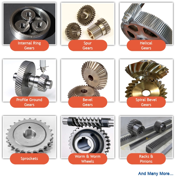
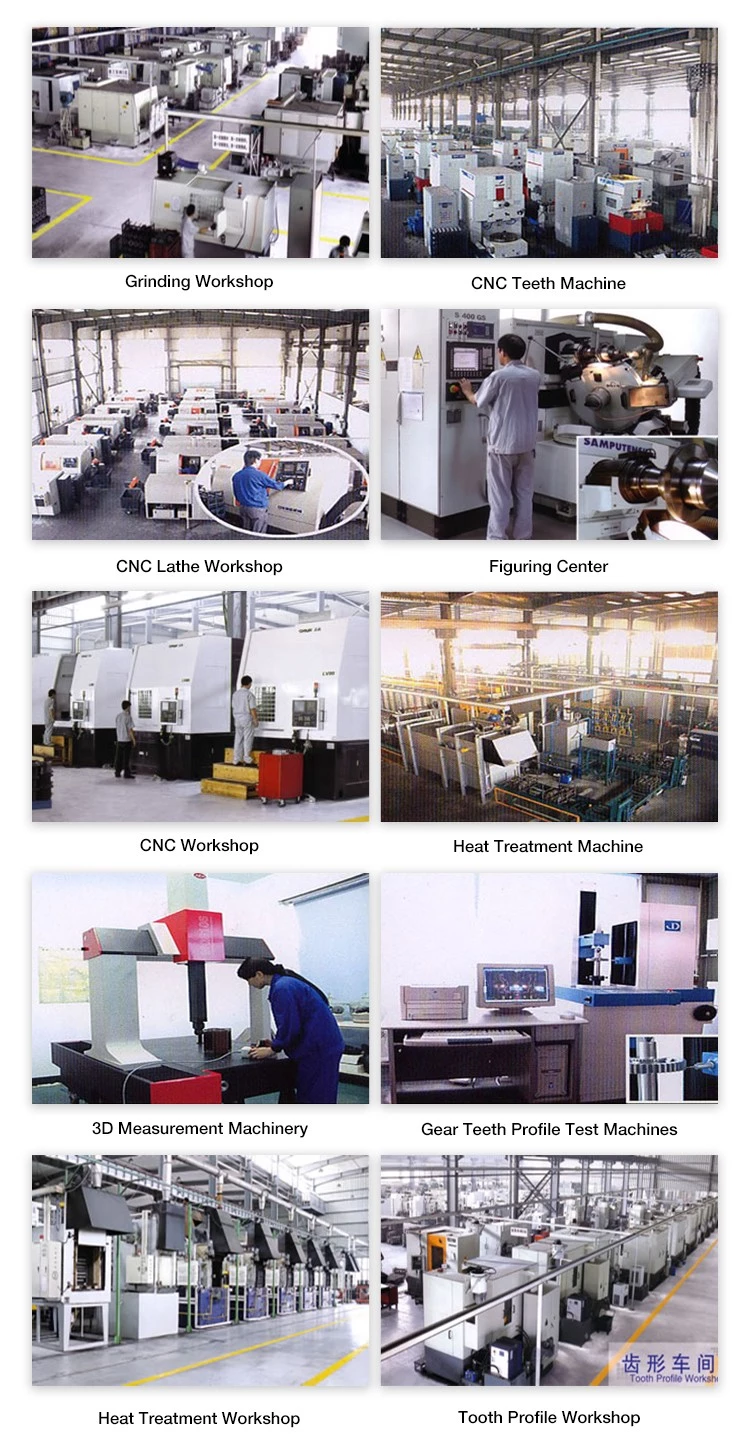
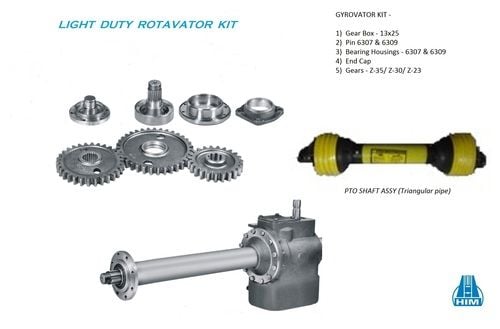
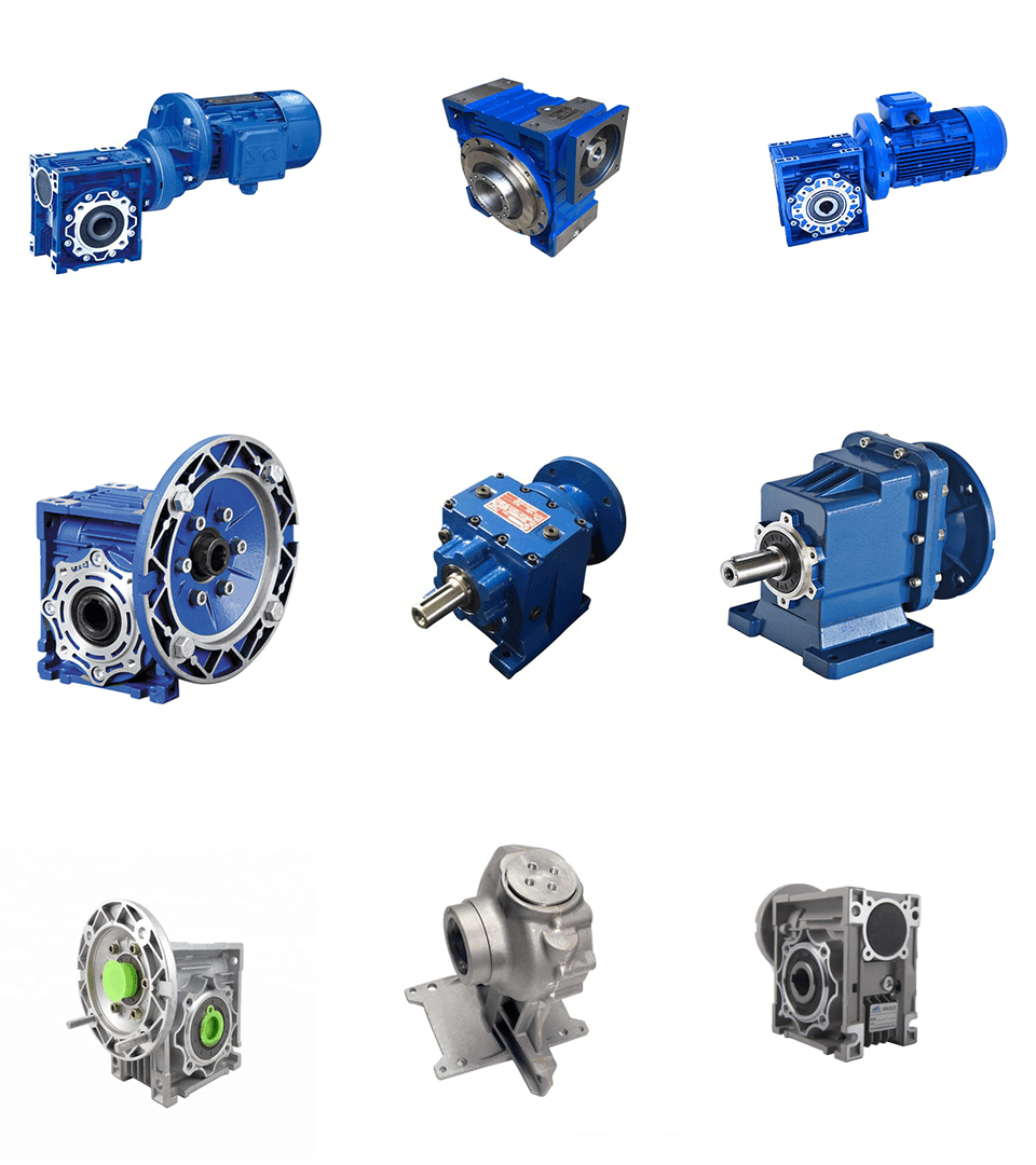
Packaging & Shipping and delivery