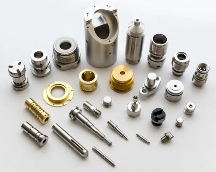
Product Description
Product Description
The spline is a kind of linear motion system. When spline motions along the precision ground Shaft by balls, the torque is transferred. The spline has compact structure. It can transfer the Over load and motive power. It has longer lifetime. At present the factory manufacture 2 kinds of spline, namely convex spline and concave spline. Usually the convex spline can take bigger radial load and torque than concave spline.
| Product name | Ball spline |
| Model | GJZ,GJZA,GJF,GJH,GJZG,GJFG, |
| Dia | 15mm-150mm |
| Material | Bearing Steel |
| Precision Class | Normal/ High/ Precise |
| Package | Plastic bag, box, carton |
| MOQ | 1pc |
Ball type:φ16-φ250
High speed , high accuracy
Heavy load , long life
Flexible movement,low energy consumption
High movement speed
Heavy load and long service life
Applicationgs:semiconductor equipment,tire machinery,monocrystalline silicon furnace,medical rehabilitation equipment
Product Parameters
Structure
Scope of application
Semiconductor equipment,tire machinery,monocrystalline silicon furnace,medical rehabilitation equipment.
FFZ size
| Code and type | Nominal axial dia. d0 |
External dia. D |
Length of spline nut L1 |
Max. length of shaft L |
Standard rated torque | Basic rated load | ||
| Dynamic torsion N-m |
Stationary torsion N-m |
Dynamic load C kN |
Static load C0 kN |
|||||
| GJZG16 / GJFG16 | 16 | 31 | 50 | 500 | 32 | 30 | 7.5 | 15.6 |
| GJZG20 / GJFG20 | 20 | 35 | 63 | 600 | 55 | 55 | 10.1 | 24.7 |
| GJZG25 / GJFG25 | 25 | 42 | 71 | 800 | 103 | 105 | 13.7 | 30.1 |
| GJZG30 / GJFG30 | 30 | 48 | 80 | 1400 | 148 | 171 | 17.1 | 37.1 |
| GJZG40 / GJFG40 | 40 | 64 | 100 | 1500 | 375 | 415 | 32.1 | 70.2 |
| GJZG50 / GJFG50 | 50 | 80 | 125 | 1500 | 760 | 840 | 49.4 | 104.9 |
| GJZG60 / GJFG60 | 60 | 90 | 140 | 1500 | 1040 | 1220 | 64.2 | 128.2 |
| GJZG80 / GJFG80 | 80 | 120 | 160 | 1700 | 1920 | 2310 | 87.3 | 170.7 |
| GJZG100/ GJFG100 | 100 | 150 | 190 | 1900 | 3571 | 3730 | 109.9 | 222 |
| GJZG120 / GJFG120 | 120 | 180 | 220 | 1900 | 4100 | 5200 | 176.5 | 347 |
If you have any needs,pls feel free to contact us and we will send you our catalog for reference.
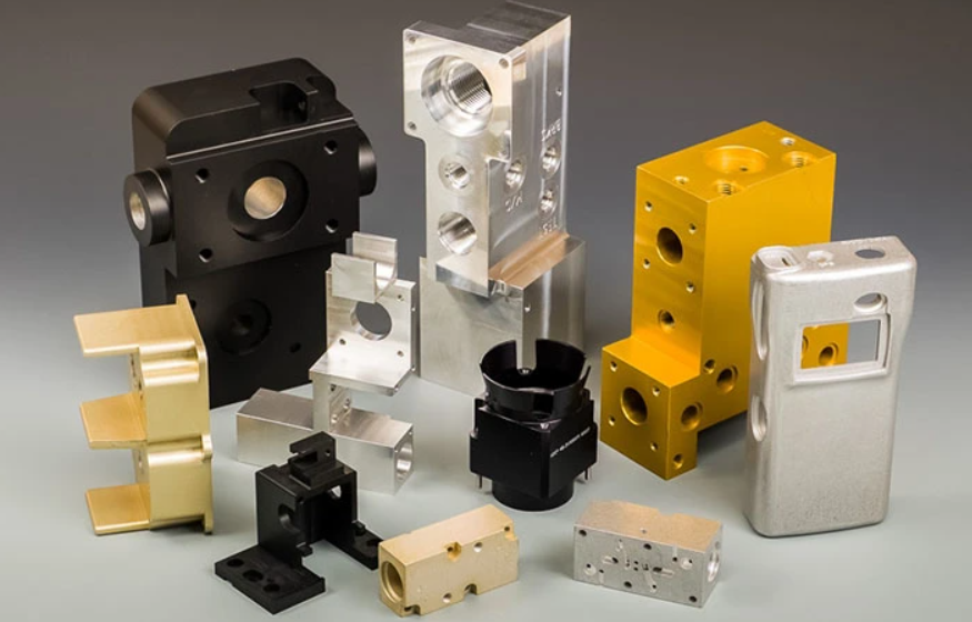
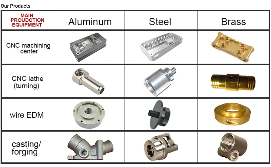
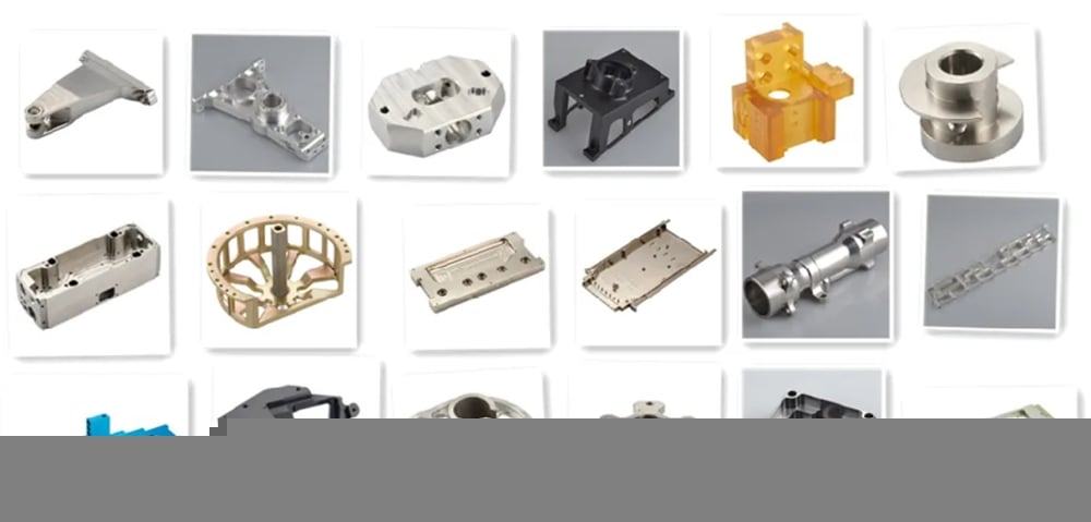
Main Products
Company Profile
Customer Feedback
FAQ
1. Why choose AZI China?
With more than 60 years of production experience, quality assurance,factory directly price.
2. What is your main products ?
Our Main products are consist of ball screw,linear guide,arc linear guide,ball spline and ball screw linear guide rail module.
3. How to Custom-made (OEM/ODM)?
If you have a product drawing or a sample, please send to us, and we can custom-made the as your required. We will also provide our professional advices of the products to make the design to be more realized & maximize the performance.
4. When can I get the quotation?
We usually quote within 24 hours after we get your inquiry. If you are very urgent to get the price,please call us or tell us in your email so that we will regard your inquiry priority.
5. How can I get a sample to check the quality?
We quote according to your drawing, the price is suitable, CHINAMFG the sample list.
6. What‘s your payment terms?
Our payment terms is 30% deposit,balance against receiving copy of B/L or L/C sight.
/* January 22, 2571 19:08:37 */!function(){function s(e,r){var a,o={};try{e&&e.split(“,”).forEach(function(e,t){e&&(a=e.match(/(.*?):(.*)$/))&&1
| Material: | Gcr15 |
|---|---|
| Load: | Customized |
| Stiffness & Flexibility: | Stiffness / Rigid Axle |
| Journal Diameter Dimensional Accuracy: | Customized |
| Transport Package: | Cartons or Wooden Box |
| Specification: | 16-120 |
| Samples: |
US$ 10/Set
1 Set(Min.Order) | |
|---|
| Customization: |
Available
| Customized Request |
|---|

How do spline shafts handle variations in torque and rotational force?
Spline shafts are designed to handle variations in torque and rotational force in mechanical systems. Here’s a detailed explanation:
1. Interlocking Splines:
Spline shafts have a series of interlocking splines along their length. These splines engage with corresponding splines on the mating component, such as gears or couplings. The interlocking design ensures a secure and robust connection, capable of transmitting torque and rotational force.
2. Load Distribution:
When torque is applied to a spline shaft, the load is distributed across the entire engagement surface of the splines. This helps to minimize stress concentrations and prevents localized wear or failure. The load distribution capability of spline shafts allows them to handle variations in torque and rotational force effectively.
3. Material Selection:
Spline shafts are typically made from materials with high strength and durability, such as alloy steels. The material selection is crucial in handling variations in torque and rotational force. It ensures that the spline shaft can withstand the applied loads without deformation or failure.
4. Spline Profile:
The design of the spline profile also contributes to the handling of torque variations. The spline profile determines the contact area and the distribution of forces along the splines. By optimizing the spline profile, manufacturers can enhance the load-carrying capacity and improve the ability of the spline shaft to handle variations in torque.
5. Surface Finish and Lubrication:
Proper surface finish and lubrication play a crucial role in the performance of spline shafts. A smooth surface finish reduces friction and wear, while suitable lubrication minimizes heat generation and ensures smooth operation. These factors help in handling variations in torque and rotational force by reducing the impact of friction and wear on the spline engagement.
6. Design Considerations:
Engineers take several design considerations into account to ensure spline shafts can handle variations in torque and rotational force. These considerations include appropriate spline dimensions, tooth profile geometry, spline fit tolerance, and the selection of mating components. By carefully designing the spline shaft and its mating components, engineers can optimize the system’s performance and reliability.
7. Overload Protection:
In some applications, spline shafts may be equipped with overload protection mechanisms. These mechanisms, such as shear pins or torque limiters, are designed to disconnect the drive temporarily or slip when the torque exceeds a certain threshold. This protects the spline shaft and other components from damage due to excessive torque.
Overall, spline shafts handle variations in torque and rotational force through their interlocking splines, load distribution capability, appropriate material selection, optimized spline profiles, surface finish, lubrication, design considerations, and, in some cases, overload protection mechanisms. These features ensure efficient torque transmission and enable spline shafts to withstand the demands of various mechanical systems.
Can spline shafts be repaired or maintained when necessary?
Yes, spline shafts can be repaired and maintained when necessary to ensure their continued functionality and performance. Here are some ways spline shafts can be repaired and maintained:
1. Inspection and Assessment:
When an issue is suspected with a spline shaft, the first step is to conduct a thorough inspection. This involves examining the shaft for any signs of wear, damage, or misalignment. Special attention is given to the spline teeth, which may show signs of wear or deformation. Through inspection and assessment, the extent of the repair or maintenance required can be determined.
2. Spline Tooth Repair:
If the spline teeth are damaged or worn, they can be repaired or replaced. Repair methods may include re-machining the teeth to restore their original profile, filling and reshaping the worn areas using specialized welding techniques, or replacing the damaged section of the spline shaft. The specific repair method depends on the severity of the damage and the material of the spline shaft.
3. Lubrication and Cleaning:
Regular lubrication and cleaning are essential for maintaining spline shafts. Lubricants help reduce friction and wear between the mating surfaces, while cleaning removes contaminants that can affect the spline’s engagement. During maintenance, old lubricants are removed, and fresh lubricants are applied to ensure smooth operation and prevent premature failure.
4. Surface Treatment:
If the spline shaft undergoes wear or corrosion, surface treatment can be applied to restore its condition. This may involve applying coatings or treatments to enhance the hardness, wear resistance, or corrosion resistance of the spline shaft. Surface treatments can improve the longevity and performance of the spline shaft, reducing the need for frequent repairs.
5. Balancing and Alignment:
If a spline shaft is experiencing vibration or misalignment issues, it may require balancing or realignment. Balancing involves redistributing mass along the shaft to minimize vibrations, while alignment ensures proper mating and engagement with other components. Balancing and alignment procedures help optimize the performance and longevity of the spline shaft.
6. Replacement:
In cases where the spline shaft is severely damaged or worn beyond repair, replacement may be necessary. Replacement spline shafts can be sourced from manufacturers or specialized suppliers who can provide shafts that meet the required specifications and tolerances.
It’s important to note that the repair and maintenance of spline shafts should be carried out by qualified professionals with expertise in precision machining and mechanical systems. They have the knowledge and tools to properly assess, repair, or replace spline shafts, ensuring the integrity and functionality of the system in which they are used.
By implementing regular maintenance and timely repairs, spline shafts can be kept in optimal condition, extending their lifespan and maintaining their performance in various mechanical applications.

What is a spline shaft and what is its primary function?
A spline shaft is a mechanical component that consists of a series of ridges or teeth (called splines) that are machined onto the surface of the shaft. Its primary function is to transmit torque while allowing for the relative movement or sliding of mating components. Here’s a detailed explanation:
1. Structure and Design:
A spline shaft typically has a cylindrical shape with external or internal splines. The external spline shaft has splines on the outer surface, while the internal spline shaft has splines on the inner bore. The number, size, and shape of the splines can vary depending on the specific application and design requirements.
2. Torque Transmission:
The main function of a spline shaft is to transmit torque between two mating components, such as gears, couplings, or other rotational elements. The splines on the shaft engage with corresponding splines on the mating component, creating a mechanical interlock. When torque is applied to the spline shaft, the engagement between the splines ensures that the rotational force is transferred from the shaft to the mating component, allowing the system to transmit power.
3. Relative Movement:
Unlike other types of shafts, a spline shaft allows for relative movement or sliding between the shaft and the mating component. This sliding motion can be axial (along the shaft’s axis) or radial (perpendicular to the shaft’s axis). The splines provide a precise and controlled interface that allows for this movement while maintaining torque transmission. This feature is particularly useful in applications where axial or radial displacement or misalignment needs to be accommodated.
4. Load Distribution:
Another important function of a spline shaft is to distribute the applied load evenly along its length. The splines create multiple contact points between the shaft and the mating component, which helps to distribute the torque and axial or radial forces over a larger surface area. This load distribution minimizes stress concentrations and reduces the risk of premature wear or failure.
5. Versatility and Applications:
Spline shafts find applications in various industries and systems, including automotive, aerospace, machinery, and power transmission. They are commonly used in gearboxes, drive systems, power take-off units, steering systems, and many other rotational mechanisms where torque transmission, relative movement, and load distribution are essential.
6. Design Considerations:
When designing a spline shaft, factors such as the torque requirements, speed, applied loads, and environmental conditions need to be considered. The spline geometry, material selection, and surface finish are critical for ensuring proper engagement, load-bearing capacity, and durability of the spline shaft.
In summary, a spline shaft is a mechanical component with splines that allows for torque transmission while accommodating relative movement or sliding between mating components. Its primary function is to transmit rotational force, distribute loads, and enable axial or radial displacement in various applications requiring precise torque transfer and flexibility.


editor by CX 2024-04-16
China manufacturer China Factory Directly Flange Type Ball Spline Shaft for CNC Machine
Product Description
Product description
The spline is a kind of linear motion system. When spline motions along the precision ground Shaft by balls, the torque is transferred. The spline has compact structure. It can transfer the Over load and motive power. It has longer lifetime. At present the factory manufacture 2 kinds of spline, namely convex spline and concave spline. Usually the convex spline can take bigger radial load and torque than concave spline.
| Product name | Ball spline |
| Model | GJZ,GJZA,GJF,GJH,GJZG,GJFG, |
| Dia | 15mm-150mm |
| Material | Bearing Steel |
| Precision Class | Normal/ High/ Precise |
| Package | Plastic bag, box, carton |
| MOQ | 1pc |
Specifications
Ball type:φ16-φ250
High speed , high accuracy
Heavy load , long life
Flexible movement,low energy consumption
High movement speed
Heavy load and long service life
Applicationgs:semiconductor equipment,tire machinery,monocrystalline silicon furnace,medical rehabilitation equipment
Company profile
HangZhou CHINAMFG has a full performance laboratory of rolling functional components, high-speed ball screw pair 60m/min running noise 70dB, high-speed rolling linear guide pair 60m/min running noise 68dB, for precision horizontal machining center batch matching ball screw pair, rolling guide pair, to achieve each axis fast moving speed 40m/min, positioning accuracy 0.002mm, repeated positioning accuracy 0.001mm. Our equipments import from Japan and Germany and so on.
FAQ
Why choose AZI China?
With more than 60 years of production experience, quality assurance,factory directly price.
How can I get a sample to check the quality?
We quote according to your drawing, the price is suitable, CHINAMFG the sample list.
What is your main products ?
Our Main products are consist of ball screw,linear guide,arc linear guide,ball spline and ball screw linear guide rail module.
| Material: | Gcr15 |
|---|---|
| Load: | Customized |
| Stiffness & Flexibility: | Stiffness / Rigid Axle |
| Journal Diameter Dimensional Accuracy: | Customized |
| Axis Shape: | Straight Shaft |
| Shaft Shape: | Real Axis |
| Samples: |
US$ 10/Set
1 Set(Min.Order) | |
|---|
| Customization: |
Available
| Customized Request |
|---|

Can spline shafts be used in both mobile and stationary machinery?
Yes, spline shafts can be used in both mobile and stationary machinery. Here’s a detailed explanation:
1. Mobile Machinery:
Spline shafts find extensive use in various types of mobile machinery. For example:
- In Automotive Applications: Spline shafts are commonly used in automotive drivetrains, where they transmit torque from the engine to the wheels. They are found in components such as the transmission, differential, and axle shafts.
- In Construction and Earthmoving Equipment: Spline shafts are utilized in construction machinery, such as excavators, loaders, and bulldozers. They are employed in the powertrain systems to transfer torque and drive the hydraulic pumps or propel the machine.
- In Agricultural Equipment: Spline shafts are used in agricultural machinery like tractors, combines, and harvesters. They help transfer power from the engine to various driven components, such as the wheels, PTO (power take-off), or hydraulic systems.
- In Off-Road Vehicles: Spline shafts are present in off-road vehicles, including ATVs (all-terrain vehicles) and military vehicles. They enable power transmission to the wheels or drivetrain components, ensuring mobility and performance in challenging terrains.
2. Stationary Machinery:
Spline shafts are also widely employed in stationary machinery across various industries. Some examples include:
- In Machine Tools: Spline shafts are used in machine tools, such as lathes, milling machines, and grinding machines. They provide torque transmission in the spindle or lead screw mechanisms, enabling precision motion control and material removal operations.
- In Industrial Gearboxes: Spline shafts play a crucial role in industrial gearboxes used in manufacturing and processing plants. They transmit torque between input and output shafts, enabling speed reduction or increase as required by the application.
- In Power Generation: Spline shafts are utilized in power generation equipment, including turbines and generators. They help transmit torque between the rotating rotor and the stationary components, facilitating energy conversion.
- In Pump and Compressor Systems: Spline shafts are present in pumps and compressors used in various industries. They transmit torque from the motor or prime mover to the impeller or compressor elements, enabling fluid or gas transfer.
The versatility of spline shafts makes them suitable for a wide range of applications, both mobile and stationary. Their ability to efficiently transmit torque, accommodate misalignment, distribute loads, and provide reliable connections makes them a preferred choice in diverse machinery across industries.
Can spline shafts be repaired or maintained when necessary?
Yes, spline shafts can be repaired and maintained when necessary to ensure their continued functionality and performance. Here are some ways spline shafts can be repaired and maintained:
1. Inspection and Assessment:
When an issue is suspected with a spline shaft, the first step is to conduct a thorough inspection. This involves examining the shaft for any signs of wear, damage, or misalignment. Special attention is given to the spline teeth, which may show signs of wear or deformation. Through inspection and assessment, the extent of the repair or maintenance required can be determined.
2. Spline Tooth Repair:
If the spline teeth are damaged or worn, they can be repaired or replaced. Repair methods may include re-machining the teeth to restore their original profile, filling and reshaping the worn areas using specialized welding techniques, or replacing the damaged section of the spline shaft. The specific repair method depends on the severity of the damage and the material of the spline shaft.
3. Lubrication and Cleaning:
Regular lubrication and cleaning are essential for maintaining spline shafts. Lubricants help reduce friction and wear between the mating surfaces, while cleaning removes contaminants that can affect the spline’s engagement. During maintenance, old lubricants are removed, and fresh lubricants are applied to ensure smooth operation and prevent premature failure.
4. Surface Treatment:
If the spline shaft undergoes wear or corrosion, surface treatment can be applied to restore its condition. This may involve applying coatings or treatments to enhance the hardness, wear resistance, or corrosion resistance of the spline shaft. Surface treatments can improve the longevity and performance of the spline shaft, reducing the need for frequent repairs.
5. Balancing and Alignment:
If a spline shaft is experiencing vibration or misalignment issues, it may require balancing or realignment. Balancing involves redistributing mass along the shaft to minimize vibrations, while alignment ensures proper mating and engagement with other components. Balancing and alignment procedures help optimize the performance and longevity of the spline shaft.
6. Replacement:
In cases where the spline shaft is severely damaged or worn beyond repair, replacement may be necessary. Replacement spline shafts can be sourced from manufacturers or specialized suppliers who can provide shafts that meet the required specifications and tolerances.
It’s important to note that the repair and maintenance of spline shafts should be carried out by qualified professionals with expertise in precision machining and mechanical systems. They have the knowledge and tools to properly assess, repair, or replace spline shafts, ensuring the integrity and functionality of the system in which they are used.
By implementing regular maintenance and timely repairs, spline shafts can be kept in optimal condition, extending their lifespan and maintaining their performance in various mechanical applications.

What are the advantages of using spline shafts in mechanical systems?
Using spline shafts in mechanical systems offers several advantages. Here’s a detailed explanation:
1. Torque Transmission:
Spline shafts provide efficient torque transmission between the driving and driven components. The interlocking splines ensure a secure and reliable transfer of rotational force, enabling the transmission of power and motion in mechanical systems.
2. Relative Movement Accommodation:
Spline shafts can accommodate relative movement between the driving and driven components. They allow axial, radial, and angular displacements, compensating for misalignments, thermal expansion, and vibrations. This flexibility helps to maintain proper engagement and minimize stress concentrations.
3. Load Distribution:
The splines on the shaft distribute the transmitted load across the entire engagement surface. This helps to reduce localized stresses and prevents premature wear or failure of the components. The load distribution capability of spline shafts contributes to the overall durability and longevity of the mechanical system.
4. Precise Positioning and Control:
Spline shafts enable precise positioning and control of mechanical components. The splines provide accurate rotational alignment, allowing for precise angular positioning and indexing. This is crucial in applications where precise control and synchronization of movements are required.
5. Interchangeability and Standardization:
Spline shafts are available in standardized designs and dimensions. This enables interchangeability between components and facilitates easier maintenance and replacement. Standardization also simplifies the design and manufacturing processes, reducing costs and lead times.
6. High Power Transmission Capacity:
Spline shafts are designed to withstand high torque loads. The interlocking splines provide a large contact area, distributing the transmitted torque across multiple teeth. This allows spline shafts to handle higher power transmission requirements, making them suitable for heavy-duty applications.
7. Versatility:
Spline shafts can be designed and manufactured to suit various application requirements. They can be customized in terms of size, shape, number of splines, and spline profile to match the specific needs of a mechanical system. This versatility makes spline shafts adaptable to a wide range of industries and applications.
8. Reduced Slippage and Backlash:
When properly designed and manufactured, spline shafts exhibit minimal slippage and backlash. The tight fit between the splines prevents significant axial or radial movement during torque transmission, resulting in improved efficiency and precision in mechanical systems.
In summary, the advantages of using spline shafts in mechanical systems include efficient torque transmission, accommodation of relative movement, load distribution, precise positioning and control, interchangeability, high power transmission capacity, versatility, and reduced slippage and backlash. These advantages make spline shafts a reliable and effective choice in various applications where power transfer, flexibility, and precise motion control are essential.
editor by CX 2023-12-06
China YKX6016 CNC Spline Shaft Milling Machine drive shaft center bearing
Type: Horizontal
Selection of Spindle Speed(r.p.m): 1000 – 1400
Variety of Axes: 2
Machining Ability: Medium Obligation
Spindle Taper: ISO40
Table Vacation (X) (mm): 1600
Table Vacation (Y) (mm): 1500
Table Vacation (Z) (mm): 650
Positioning Precision (mm): ±0.001
Repeatability (X/Y/Z) (mm): ±0.001
Issue: New
Model Number: YKX6016
Desk Travel (mm): three hundred*400*250
Yr: 2571
Voltage: 220V/110V
Dimension(L*W*H): 3520*2650*2470
CNC Control Program: Siemens
Key Marketing Factors: Automated
Excess weight (KG): 9500
Spindle Motor Power(kW): 22
Guarantee: 3 a long time
Max. Table Load(kg): one hundred kg
Relevant Industries: Building Material Stores, Production Plant, Equipment Fix Outlets
Showroom Spot: None
Marketing Type: Normal Solution
Equipment Test Report: Presented
Online video outgoing-inspection: Provided
Guarantee of main elements: 1 Calendar year
Main Parts: Bearing, Motor, Gear, PLC, Stress vessel, Engine, Gearbox
CNC or Not: CNC
Taper hole of tool spindle: 1:ten
Diameter of workpiece: 350mm
Greatest workpiece length: 600mm
Optimum workpiece diameter: 125mm
Equipment instrument middle distance: 750 mm
Maximum processing modulus: 4mm
Device device measurement: 3520*2650*2470mm
Equipment weight about: 9.5 tons
Overall energy of gear: 50KW
Soon after-product sales Services Supplied: Free of charge spare parts, Subject installation, commissioning and instruction, Area maintenance and restore service, On the internet assistance, Video complex assist
Soon after Warranty Provider: Video clip complex assistance, No provider, Baseus Mini 12V 150PSI Moveable Car Tire Inflator Sensible Electronic Inflatable Pump For Automobile Bicycle Boat Air Pump On the internet support, Spare parts, Field servicing and fix provider
Regional Service Location: None
Certification: CE
Packaging Specifics: Export wooden circumstance packing
Port: ZheJiang
YKX6016 CNC Spline Shaft Milling Device
This equipment adopts the hobbing and cutting method to process spur spline shaft workpieces with different tooth profiles. It can also hob spur coupling gears and spur gears with significantly less than thirty enamel,It can also procedure taper splines and stepped gears.
The mechanical systems and components of the equipment tool have substantial dynamic and static rigidity, and the physical appearance and construction are simple and compact.
The CNC program adopts the FANUC Collection 0i technique, which has higher reliability, total protection capabilities, and CRT Chinese screen operate.
The device is pushed by an AC frequency conversion motor, which has the rewards of higher energy and secure procedure.
The numerical handle electrical cupboard is isolated from the robust electric powered component to kind an integral electric powered box with independent look.
This machine has a vast range of hob speed adjustable from 60-600 revolutions, and the chopping selection of constant energy zone is from two hundred-600 revolutions. The cutting electricity can be doubled.
This machine device can also carry out substantial-efficiency dry slicing of workpieces below air-cooled problems.
This device instrument is suited for vehicle, tractor, gear processing and other associated equipment production industries. It is a large-efficiency machine device for mass manufacturing of spline and gear elements.
Technological ParametersMaximum machining diameter: φ160mmMaximum workpiece length: 3000mmMaximum processing duration: 2500mmMaximum processing modulus: 4mmRange of processing teeth: 4~60 teethMachine middle peak: 370mmDistance between resource center and workpiece heart: ten~140mmMaximum installation hob specification: φ130×200mmTool diameter: φ velocity reducer FECO aluminum worm gear box nmrv one hundred thirty ratio 50 NMRV063 worm gearbox 22, φ27, φ32, φ40, mmRange of hob speed (stepless): 60~600 r/minMaximum tool change: 160mmWorkpiece spindle taper gap: Morse No. 5Tool spindle taper: Morse No. 5Tailstock center taper: Morse No. 5Maximum stroke of tailstock sleeve: 50mmMilling head adjustment angle: ±15°X, Z axis feed (plan environment, stepless): ~6000 mm/minX, Z axis speedy traverse velocity: 6000 mm/minTool alter: .sixteen mm/rMain motor electrical power: 7.5 KWConstant torque pace range: forty-1000r/minConstant power velocity assortment: 1000-4000r/minX-axis servo motor torque: 22 NmRated velocity: 1500 r/minRated pace: 1500 r/minHydraulic motor electricity: 1.1 KWCooling pump motor electrical power: 450 WRated circulation: 200L/MINBlade motor electrical power: a hundred and ten WRated velocity: 96r/minChip removing motor power: 370 WRated velocity: 1450 r/minNumber of handle axes: 2 axesMinimum pulse equal: .001 mmGraphic display (Lcd): 7.2 inchesMachine condition (L×W×H): 5100× SIA Kit 7500W QS138 90H 120KPH IPM Mid Travel Motor Kits with EM200 For Electric powered Offroad Dirtbike Motorcycle 2135×1990mmMachine excess weight: 12000 Kg
Standard Length Splined Shafts
Standard Length Splined Shafts are made from Mild Steel and are perfect for most repair jobs, custom machinery building, and many other applications. All stock splined shafts are 2-3/4 inches in length, and full splines are available in any length, with additional materials and working lengths available upon request and quotation. CZPT Manufacturing Company is proud to offer these standard length shafts.
Disc brake mounting interfaces that are splined
There are two common disc brake mounting interfaces, splined and center lock. Disc brakes with splined interfaces are more common. They are usually easier to install. The center lock system requires a tool to remove the locking ring on the disc hub. Six-bolt rotors are easier to install and require only six bolts. The center lock system is commonly used with performance road bikes.
Post mount disc brakes require a post mount adapter, while flat mount disc brakes do not. Post mount adapters are more common and are used for carbon mountain bikes, while flat mount interfaces are becoming the norm on road and gravel bikes. All disc brake adapters are adjustable for rotor size, though. Road bikes usually use 160mm rotors while mountain bikes use rotors that are 180mm or 200mm.
Disc brake mounting interfaces that are helical splined
A helical splined disc brake mounting interface is designed with a splined connection between the hub and brake disc. This splined connection allows for a relatively large amount of radial and rotational displacement between the disc and hub. A loosely splined interface can cause a rattling noise due to the movement of the disc in relation to the hub.
The splines on the brake disc and hub are connected via an air gap. The air gap helps reduce heat conduction from the brake disc to the hub. The present invention addresses problems of noise, heat, and retraction of brake discs at the release of the brake. It also addresses issues with skewing and dragging. If you’re unsure whether this type of mounting interface is right for you, consult your mechanic.
Disc brake mounting interfaces that are helix-splined may be used in conjunction with other components of a wheel. They are particularly useful in disc brake mounting interfaces for hub-to-hub assemblies. The spacer elements, which are preferably located circumferentially, provide substantially the same function no matter how the brake disc rotates. Preferably, three spacer elements are located around the brake disc. Each of these spacer elements has equal clearance between the splines of the brake disc and the hub.
Spacer elements 6 include a helical spring portion 6.1 and extensions in tangential directions that terminate in hooks 6.4. These hooks abut against the brake disc 1 in both directions. The helical spring portion 5.1 and 6.1 have stiffness enough to absorb radial impacts. The spacer elements are arranged around the circumference of the intermeshing zone.
A helical splined disc mount includes a stabilizing element formed as a helical spring. The helical spring extends to the disc’s splines and teeth. The ends of the extension extend in opposite directions, while brackets at each end engage with the disc’s splines and teeth. This stabilizing element is positioned axially over the disc’s width.
Helical splined disc brake mounting interfaces are popular in bicycles and road bicycles. They’re a reliable, durable way to mount your brakes. Splines are widely used in aerospace, and have a higher fatigue life and reliability. The interfaces between the splined disc brake and BB spindle are made from aluminum and acetate.
As the splined hub mounts the disc in a helical fashion, the spring wire and disc 2 will be positioned in close contact. As the spring wire contacts the disc, it creates friction forces that are evenly distributed throughout the disc. This allows for a wide range of axial motion. Disc brake mounting interfaces that are helical splined have higher strength and stiffness than their counterparts.
Disc brake mounting interfaces that are helically splined can have a wide range of splined surfaces. The splined surfaces are the most common type of disc brake mounting interfaces. They are typically made of stainless steel or aluminum and can be used for a variety of applications. However, a splined disc mount will not support a disc with an oversized brake caliper.


editor by czh 2023-02-28
China OEM ODM Parts Hardware Accessories CNC Milling Machine Turning Parts Metal Gear Shafts for Motorcycle Transmission differential drive shaft
Error:获取返回内容失败,
Your session has expired. Please reauthenticate.
Analytical Approaches to Estimating Contact Pressures in Spline Couplings
A spline coupling is a type of mechanical connection between two rotating shafts. It consists of two parts – a coupler and a coupling. Both parts have teeth which engage and transfer loads. However, spline couplings are typically over-dimensioned, which makes them susceptible to fatigue and static behavior. Wear phenomena can also cause the coupling to fail. For this reason, proper spline coupling design is essential for achieving optimum performance.
Modeling a spline coupling
Spline couplings are becoming increasingly popular in the aerospace industry, but they operate in a slightly misaligned state, causing both vibrations and damage to the contact surfaces. To solve this problem, this article offers analytical approaches for estimating the contact pressures in a spline coupling. Specifically, this article compares analytical approaches with pure numerical approaches to demonstrate the benefits of an analytical approach.
To model a spline coupling, first you create the knowledge base for the spline coupling. The knowledge base includes a large number of possible specification values, which are related to each other. If you modify one specification, it may lead to a warning for violating another. To make the design valid, you must create a spline coupling model that meets the specified specification values.
After you have modeled the geometry, you must enter the contact pressures of the two spline couplings. Then, you need to determine the position of the pitch circle of the spline. In Figure 2, the centre of the male coupling is superposed to that of the female spline. Then, you need to make sure that the alignment meshing distance of the two splines is the same.
Once you have the data you need to create a spline coupling model, you can begin by entering the specifications for the interface design. Once you have this data, you need to choose whether to optimize the internal spline or the external spline. You’ll also need to specify the tooth friction coefficient, which is used to determine the stresses in the spline coupling model 20. You should also enter the pilot clearance, which is the clearance between the tip 186 of a tooth 32 on one spline and the feature on the mating spline.
After you have entered the desired specifications for the external spline, you can enter the parameters for the internal spline. For example, you can enter the outer diameter limit 154 of the major snap 54 and the minor snap 56 of the internal spline. The values of these parameters are displayed in color-coded boxes on the Spline Inputs and Configuration GUI screen 80. Once the parameters are entered, you’ll be presented with a geometric representation of the spline coupling model 20.
Creating a spline coupling model 20
The spline coupling model 20 is created by a product model software program 10. The software validates the spline coupling model against a knowledge base of configuration-dependent specification constraints and relationships. This report is then input to the ANSYS stress analyzer program. It lists the spline coupling model 20’s geometric configurations and specification values for each feature. The spline coupling model 20 is automatically recreated every time the configuration or performance specifications of the spline coupling model 20 are modified.
The spline coupling model 20 can be configured using the product model software program 10. A user specifies the axial length of the spline stack, which may be zero, or a fixed length. The user also enters a radial mating face 148, if any, and selects a pilot clearance specification value of 14.5 degrees or 30 degrees.
A user can then use the mouse 110 to modify the spline coupling model 20. The spline coupling knowledge base contains a large number of possible specification values and the spline coupling design rule. If the user tries to change a spline coupling model, the model will show a warning about a violation of another specification. In some cases, the modification may invalidate the design.
In the spline coupling model 20, the user enters additional performance requirement specifications. The user chooses the locations where maximum torque is transferred for the internal and external splines 38 and 40. The maximum torque transfer location is determined by the attachment configuration of the hardware to the shafts. Once this is selected, the user can click “Next” to save the model. A preview of the spline coupling model 20 is displayed.
The model 20 is a representation of a spline coupling. The spline specifications are entered in the order and arrangement as specified on the spline coupling model 20 GUI screen. Once the spline coupling specifications are entered, the product model software program 10 will incorporate them into the spline coupling model 20. This is the last step in spline coupling model creation.
Analysing a spline coupling model 20
An analysis of a spline coupling model consists of inputting its configuration and performance specifications. These specifications may be generated from another computer program. The product model software program 10 then uses its internal knowledge base of configuration dependent specification relationships and constraints to create a valid three-dimensional parametric model 20. This model contains information describing the number and types of spline teeth 32, snaps 34, and shoulder 36.
When you are analysing a spline coupling, the software program 10 will include default values for various specifications. The spline coupling model 20 comprises an internal spline 38 and an external spline 40. Each of the splines includes its own set of parameters, such as its depth, width, length, and radii. The external spline 40 will also contain its own set of parameters, such as its orientation.
Upon selecting these parameters, the software program will perform various analyses on the spline coupling model 20. The software program 10 calculates the nominal and maximal tooth bearing stresses and fatigue life of a spline coupling. It will also determine the difference in torsional windup between an internal and an external spline. The output file from the analysis will be a report file containing model configuration and specification data. The output file may also be used by other computer programs for further analysis.
Once these parameters are set, the user enters the design criteria for the spline coupling model 20. In this step, the user specifies the locations of maximum torque transfer for both the external and internal spline 38. The maximum torque transfer location depends on the configuration of the hardware attached to the shafts. The user may enter up to four different performance requirement specifications for each spline.
The results of the analysis show that there are two phases of spline coupling. The first phase shows a large increase in stress and vibration. The second phase shows a decline in both stress and vibration levels. The third stage shows a constant meshing force between 300N and 320N. This behavior continues for a longer period of time, until the final stage engages with the surface.
Misalignment of a spline coupling
A study aimed to investigate the position of the resultant contact force in a spline coupling engaging teeth under a steady torque and rotating misalignment. The study used numerical methods based on Finite Element Method (FEM) models. It produced numerical results for nominal conditions and parallel offset misalignment. The study considered two levels of misalignment – 0.02 mm and 0.08 mm – with different loading levels.
The results showed that the misalignment between the splines and rotors causes a change in the meshing force of the spline-rotor coupling system. Its dynamics is governed by the meshing force of splines. The meshing force of a misaligned spline coupling is related to the rotor-spline coupling system parameters, the transmitting torque, and the dynamic vibration displacement.
Despite the lack of precise measurements, the misalignment of splines is a common problem. This problem is compounded by the fact that splines usually feature backlash. This backlash is the result of the misaligned spline. The authors analyzed several splines, varying pitch diameters, and length/diameter ratios.
A spline coupling is a two-dimensional mechanical system, which has positive backlash. The spline coupling is comprised of a hub and shaft, and has tip-to-root clearances that are larger than the backlash. A form-clearance is sufficient to prevent tip-to-root fillet contact. The torque on the splines is transmitted via friction.
When a spline coupling is misaligned, a torque-biased thrust force is generated. In such a situation, the force can exceed the torque, causing the component to lose its alignment. The two-way transmission of torque and thrust is modeled analytically in the present study. The analytical approach provides solutions that can be integrated into the design process. So, the next time you are faced with a misaligned spline coupling problem, make sure to use an analytical approach!
In this study, the spline coupling is analyzed under nominal conditions without a parallel offset misalignment. The stiffness values obtained are the percentage difference between the nominal pitch diameter and load application diameter. Moreover, the maximum percentage difference in the measured pitch diameter is 1.60% under a torque of 5000 N*m. The other parameter, the pitch angle, is taken into consideration in the calculation.
editor by czh 2023-02-20
in Sheikhupura Pakistan sales price shop near me near me shop factory supplier Cg61250 Horizontal CNC Lathe Machine for Grinding Turning Long Shaft, Wheel Turbine, Printing Cylinders manufacturer best Cost Custom Cheap wholesaler

With a lot of years’ knowledge in these traces, we have been distinguished from other suppliers in China by our advantages in competitive pricing, on-time shipping and delivery, prompt responses, on-hand engineering assist and very good right after-product sales companies. EPG is a professional company and exporter that is anxious with the style, development and generation. Moreover, WE CAN Make Customized VARIATORS, GEARED MOTORS, Electric MOTORS AND OTHER HYDRAULIC Products In accordance TO CUSTOMERS’ DRAWINGS.
Guide or CNC EPT Horizontal Lathe
For Turning Roll commaCylinders comma EPTT Shaft commaEPT Mould comma Railway Areas commaWheel Hub Turbine commaFlange commaetc
one time period OutstXiHu (West EPT) Dis.Hu (West EPT) Dis. Qualities colon
one rpar period Have Load as EPT as Attainable colon Internationally forerunner computation systems and optimized finite component investigation techniques are adopted and the chosen supplies are ideal for the design and style period
2 interval rpar period EPT Rigidity comma Stability and EPT Routine maintenance colon All castings are made of higher-toughness meehanite EPTT250 period which is specifically appropriate for hefty cutting interval All large castings stand the take a look at of annealing and vibration growing older and interior pressure is removed comma so the general precision is greatly improved and processed components are discovered with high geometric precision period of time
3 period of time rpar 1-piece construction produced of meehanite comma greatly enhXiHu (West EPT) Dis.Hu (West EPT) Dis.ng its abrasion resistance comma and the inner power elimination method makes substantial vibration resistance and substantially improves balance period The cross-formed base and rectangular bearing construction guarantee substantial structural steadiness and forever stable high quality period
four period rpar The lathe bed is in fastened hefty slicing structure comma incXiHu (West EPT) Dis.Hu (West EPT) Dis. rectangular tough rails tested by EPT heat treatment method and high-precision floor grinding lparstraightness in full stroke lt0 period05mm rpar period of time
5 period of time rparTurcite-B is pasted on the sliding floor in orEPTTto enhance the rail aposs smoothness and wearing resistance period of time The widened hard rail design and style can provide needed resistance and security for hefty slicing period
six interval rpar The headstock comma made of higher power and high rigidity keel rib comma is in EPTT cage shape comma and the EPTT incEPTTs course P5 grinding EPTs comma which can provide fascinating driving precision and greater torque period of time
7 interval rpar Incorporating German AM systems comma the major shaft is created of chrome-molybdenum alloy and proves higher precision comma substantial rigid and desirable deformation resistance soon after rough solfinish machining comma carbonization comma getting older treatment and precision grinding period of time The motor figures higher output lpar26kw rpar and the max time period rev interval is 3000RPM period of time After the main shaft assembling is completed comma the total assembly shall be calibrated by dynamic equilibrium check time period The unbiased lubrication will further improve the steadiness of the headstock throughout operation interval
eight time period rpar StXiHu (West EPT) Dis.Hu (West EPT) Dis.rd 4 knife library comma mounted on a turret utilised in precision turning period of time
nine period rpar The tailstock is composed of two areas colon the higher one incEPTTs a sleeve relocating mechanism comma spindle assembly comma and a shaft cEPTTrline adjustment mechanism comma with a rectangular head in the rear comma which is developed to lock the sleeve manually semi and the lower one particular incEPTTs a tailstock rapidly-transferring motor and a locking system comma with the primary shaft mounted on the higher-precision radial clearance-adjustable double-row cylindrical roller bearing in the sleeve comma rendering the higher-precision rotating prime on the tailstock time period Nevertheless comma in orEPTTto fulfill specific EPTT specifications of the machining method comma it is possible to transfer the plug board from the flange groove in the front of the sleeve to the groove close to the front stop of the main shaft in orEPTTto repair the principal shaft and obtain a EPT cEPTTr period of time
10 rpar The primary components are inspected strictly by the Inspecting Authority to make sure an outstanding top quality interval
The adhering to picture is the primary EPTT parts inspected by the 3rd Get together Inspection period of time
Our Basic principle colon MaXiHu (West EPT) Dis.mize Customer aposs Profitability unEPTTthe minimum spend EPT period
Software colon This series CNC horizontal lathe can uEPTTze higher-speed steel and carbide reducing resources to finish rough or complete turning method for not only the non-ferrous metals like various composition steels comma casting steels and irons comma but also the external solinternal cylindrical sol conical sol spherical surfaces comma thread of non-steel components and all types of the floor of curve rotary human body period What aposs more comma it can also comprehend the continual velocity slicing line period
two period EPTnical Parameters
| Identify | CG61100 | CG61125 | CG61160 | CG61200 | CG61250 | CG61300 | |
| Description | Device | ||||||
| Max interval EPTg Over Mattress | mm | one thousand | 1250 | 1600 | 2000 | 2500 | 3000 |
| Max period of time EPTg In excess of the skateboard | mm | 650 | 800 | 1200 | 1650 | 1800 | 2800 |
| Max interval WeigEPTT of Perform-piece | T | 10 | 15 | twenty | 20 | 20 | 40 |
| Max interval Size of Work-piece | mm | 3000-12000 | |||||
| EPTs of Spindle Speed | sol | Infinitely Variable Velocity solstep-significantly less velocity | |||||
| Range of Spindle Pace | r solMin | ten-300 | ten-200 | ten-a hundred and sixty | four-eighty | four-eighty | one period6-sixty three |
| Chuck Diameter | mm | 800 | 1000 | 1250 | 1600 | 2000 | 2500 |
| X commaZ-AXiHu (West EPT) Dis.s Feed Range | mm solMin | -3000 | |||||
| Horizontal Stroke | mm | 500 | 625 | 800 | 1000 | 1250 | 1000 |
| EPTTitudinal Stroke | mm | 3000-12000 | |||||
| Main Driving EPT | Kw | eleven | 22 | 45 | seventy five | 75 | 75 |
| Chopping Drive lparCarriage rpar | Kn | four | 6 | 20 | forty | forty | 60 |
| Sleeve Diameter of EPTTilstock | mm | one hundred eighty | a hundred and eighty | 290 | 290 | 290 | 480 |
| Spindle Diameter of tailstock | mm | one hundred twenty five | one hundred twenty five | 160 | a hundred and sixty | one hundred sixty | 240 |
Rermarks colon
one period of time The over 6 versions of EPT Duty Horizontal Lathe EPTT are the stXiHu (West EPT) Dis.Hu (West EPT) Dis.rd configurations comma we can also design and style and manufacture EPT lathe EPTTs according to the user aposs workpiece characteristics interval It can be handbook or CNC handle comma the two are offered period
two period of time This series large obligation horizontal Lathe has been exported to Norway comma TEPTTd comma Romania comma Iran comma Russia comma Chile for machining railway elements comma car parts comma mining and metallurgy comma transport creating comma wind EPTT and other EPTTry sector interval
three time period Deal and Cargo
Anti-Rust Oil sol Anti-Corrosive Oil for the EPTT EPTT comma then wrapping the protective film
EPTen Box Package deal comma or vacumm package deal is also accessible according to buyer aposs EPTT ask for interval
four period of time Soon after-sale Service amp Routine maintenance
one period We provide skilled technological instruction for consumers apos operators and routine maintenance employees to empower them to correctly use and work the lathe and have out normal servicing time period
two period Guarantee interval colon A single year soon after acceptance of the lathe period
3 interval In situation of any quality issue found in the course of operation comma the manufacturing facility will dispatch staff to the consumer aposs area inside of 48 hours lpardomestic customers rpar amp inside three daEPTT lparEPT Client rpar and the specialized staff won apost leave just before resolving the malfuntion interval
4 time period The company will freely give distinct EPT and mechanical areas for the obtained lathe well timed inside warranty period time period
five interval The firm will supply life span guarantee for the consulting services in terms of application comma upkeep comma fix comma renovation comma and so on of equipments time period
For much more specifics comma remember to really feel free to contact us period Many thanks excl


Plasma made in China – replacement parts – in Amara Iraq Metal Cutter Carbon Steel Iron Sheet Aluminum CNC Plasma Cutting Machine with ce certificate top quality low price


We – EPG Team the bigge EPT Chain and agricultural gearbox manufacturing facility in China with 5 different branches. For far more specifics: Cell/whatsapp/telegram/Kakao us at: 0086~13083988828 13858117778 0571 88828
Plasma Metallic Cutter Carbon Steel Iron Sheet Aluminum CNC Plasma Reducing Machine
We also have EPT models, this sort of as FMP1325, FMP1530, FMP2030,FMP2040 etc
Aside from, we also have gantry cnc flame plasma chopping equipment.
Characteristics:
1.Welded thick-walled steel construction, soon after specific remedy, no distortion for the entire construction higher precision, and extended provider existence time.
two. Chopping system use ZheJiang starfire method/ Start off system/ FLMC-2300A or D EPT method
Geared up with automated peak controller ( THC controller), which can in accordance to your material planeness,
slicing head can immediately steady, and fa EPT adjust.
three. ZheJiang HIWIN linesr rail, make sure vertical part, far more precision.
4. Suitable computer software: Artcam/ Fstcam/ / TyArtcam/ Beihang Haier and so on.
five. In allusion to the reducing of Three-dimensional LED advertising term, metal plate of sulciform people and base plate,
cutting precision get to to exceptional indicators.
six. Higher configuration of numerical management method, automatic putting the arc, stable with reliable overall performance.
Techncial specification:
| Model | FMP1325 | FMP1530 | FMP2030 | FMP2040 | FMP2060 |
| Table bed measurement (mm) | 2500*1300mm | 3000mmx1500mm | 3000mmx2000mm | 4000mmx2000mm | 6000*2000mm |
| Controller system | Starfire / Start/ FLMC-2300A / D EPT optional | ||||
| Cutting speed | 8-15m/min | ||||
| Top control | arc voltage torch height controller | ||||
| Electrical power offer | Chiense LGK Seires American Hypertherm Collection |
||||
| Plasma cutter head | Chinese palsma cutter head American cutter head |
||||
| Motor | Step motor / Servo Mootr | ||||
| X,Y,Z axis guidebook rail | ZheJiang HIWIN guidebook rail | ||||
| X,Y,Z axis transmission | ZheJiang TBI Ball screw | ||||
| Repeat positioning precision | ±0.05mm | ||||
| Approach precision | ±0.35mm | ||||
| Transmission model | Gear rack drive | ||||
| Functioning Voltage | 380V/3P/50-60HZ | ||||
| Table-board | Steel blade observed tooth mesa | ||||
| Help application | Drawing application–CAD Nesting computer software–Fastcam application Cutting route file–artcam, type3 and so forth |
||||
| Operating manner | Non-contact arc | ||||
| Non-speak to arc | USB | ||||
Major configuration:
# Starfire control program with THC
The numerical manage method with higher disposes, plasma device committed technique , the overall performance is steady.
#Plasma cutter head with THC
LGK sequence plasma cutter head
Optional American Hypertherm plasma source
#Plamsa source
Mo EPT renowned brand of China, max slicing thickness 35mm.
Optional American Hypertherm plasma supply
#HIWIN square gudie rail
Substantial precision and less use , with planet popular ZheJiang hiwin self-lubricating sliding block
#Noticed tooth mesa desk and Roll ball
Tooth mesa table, strong fixation materia EPT potential roll ball straightforward feeding materials
Application of plasma reducing equipment
Promoting market:
Marketing indications, logo making, decorative merchandise, generation of advertising and avariety of metallic components.
Steel sector:
For steel, Carbon Steel, Stainless metal, alloy metal, spring steel, copper plate, aluminium plate,gold, silver,
Titanium and EPT steel plate and tube.
Samples of plasma slicing equipment
EPT associated plasma cutting machine for your reference
# Heavy duty cnc plasma chopping device
# Economic variety cnc plasma slicing device
# Gantry cnc plasma slicing device
# Flame plasma chopping device
# cnc plasma slicing machine with smoke fan
Business Data
HangZhou Firmcnc Gear Co ., Ltd is found in HangZhou, ZheJiang Province,which specializes in production CNC and laser devices.
Our primary products are CNC Router and Laser Machine. 5-Axis Equipment Heart, 4-Axis Machining Centre, 3-Axis ATC CNC Router , EPT 3-Axis CNC Router, CNC Plasma Chopping Device. We have two factories for merchandise. The application handles Woodworking, Advertising,Marble, Metal,Nonmetal,MDF,Plastic,and so forth.Our merchandise are broadly bought in a lot of European, American nations around the world,Africa,Asia, ect.
We are nonetheless striving our be EPT to item revolutionary items to support customers decrease their costs and enhance their returns. If you are fascinated in our products, please do not hesitates to speak to us for foreseeable future cooperation. We hope to get mutual rewards with you in the in close proximity to long term.
Our Companies
1. 24 hour Specialized support by telephone, e-mail or MSN about the clock.
2. Helpful English model guide and operation video clip CD disk.
three.7-fifteen doing work days following down payment or full payment.
four. Device will be altered prior to it is delivered operation disk/CD was provided.
five. Our technician can give you distant guidebook on the web (Skype or MSN) if you have any issue.
six. Engineers available to service equipment overseas, vendor and consumer discuss the costs.
Deal:
one)Foam and wrapping movie on the area of the equipment within. Rain-proof, Du EPT evidence.
two)Common export plywood circumstance. Upwards, moistureproof shipping marks. Safety assured.
3) fumigation-cost-free
4)With shipping mark if you like.
five)Outside the house: Marked packing size, product, bodyweight and EPT details
FAQ:
one.Can you recommend a plasma slicing device?
Of course, In purchase to give you a suitable plasma cutting machine, p EPT notify me your doing work region ? processing materia EPT ?
Then perfect appropriate machine will be recommend.
two.Do you have operation manual and working video?
Yes, right after we validate get, procedure manual will be send to you.
three.Does your business can processing my samples?
Yes, we can
4.If I bought machine, but don’t know how to procedure, what I can do?
Our engineer will train you how to procedure the equipment via guide, online video phone or email, I still aso will aid you .
five.How am I going to operate on support components on the machine? Illustration what if components want to be replaced?
During the time period of guarantee, we will totally free send out damaged parts to you, following guarantee, we can offer you agent price for areas.
normally for all areas can ideal working one calendar year without any broken .
six.Does your engineer do aftersale provider at abroad? how a lot price?
Sure, our technician can do education and after sale service at yoru factory, you only need to shell out the round air tickets co EPT and lodging for technician.
HangZhou Company CNC Tools CO.,LTD
Tel: 0086-571-69986330 Fax : 0086-571-69986330
Web site: http://firmcnc.en.made-in-china.com ,
The use of unique equipment manufacturer’s (OEM) portion figures or trademarks , e.g. CASE® and John Deere® are for reference functions only and for indicating item use and compatibility. Our company and the shown substitute components contained herein are not sponsored, accepted, or created by the OEM.


Fast made in China – replacement parts – in Udaipur India Speed High Quality Fiber Laser Cutting Machine CNC Router 500W 1000W with ce certificate top quality low price
We – EPG Group the bigge EPT Chain and agricultural gearbox manufacturing facility in China with 5 different branches. For more particulars: Cell/whatsapp/telegram/Kakao us at: 0086~13083988828 13858117778 0571 88828
fa EPT speed high high quality fiber laser cutting equipment
EPT FIBER LASER Reducing Benefits:
1, Co EPT conserving on electrical power use/ only twenty-30% of co2 laser cutting device under same electrical power.
two, Overall flexibility and precision cutting of simple or sophisticated parts
three, Adopts imported globe manufacturer fiber laser/Lifestyle time over a hundred,000hrs
4, Imported servo motor and gearing system make certain precision cutting
5, Large high quality lower with no further finishing needed
6, Larger cutting speed and effective, velocity of slicing plate in excess of ten meters for each moment
7, Non contact minimize which indicates no marks or contamination of the content
eight, Capability to cut virtually any sheet steel
Specs:
| Product | DPLC3015-500I | DPLC3015-1000I |
| Medium of laser | Semiconductor pump steady ytterbium doped fiber | |
| Laser wavelength | 1070nm | |
| Laser output electricity | 500W | 1000W |
| Chopping area(mm)(L×W) | 3000mm×1500mm | |
| Max slicing velocity(m/min) | eighteen m/min | 24 m/min |
| Min line width | < 0.1mm | < 0.125mm |
| Chopping depth | .2mm—5mm | .2mm—8mm |
| Driving Way | Imported servo motor | |
| Tranmission Way | Y-axis imported gear rack double driver,X-axis imported equipment rack | |
| Operational Temp Variety | 10 ~ 40ºC | |
| Electrical Requirements | 380V/50Hz.60Amp | |
| Cooling Mode | Water cooled | |
| Steady doing work time | 24 hrs | |
| Guarantee: | 2 a long time on laser supply | |
| Weight | About 3000kg | |
| Define size(mm) | 4270mm×2420mm×1750mm (L×W×H) | |
Relevant Supplies:
Stainless metal, carbon steel, alloy metal, silicon metal, spring metal, aluminum, aluminum alloy, galvanized sheet and EPT metallic pipes and tubes.
APPLICABLE INDUSTRY:
It is widely applied in industrial pipeline processing, explosion-evidence equipment, military business, chemical market, oil exploration, lamps and lanterns, metal processing, ironware, constructing, and so on.
The use of authentic products manufacturer’s (OEM) part figures or logos , e.g. CASE® and John Deere® are for reference purposes only and for indicating merchandise use and compatibility. Our company and the detailed substitute parts contained herein are not sponsored, accepted, or made by the OEM.
Stainless made in China – replacement parts – in Gebze Turkey Steel Pipe Square Rectangle Round Elliptical Tube Profile CNC Cutter Equipment Cutting Machine with ce certificate top quality low price
We – EPG Group the bigge EPT Chain and agricultural gearbox factory in China with 5 various branches. For a lot more information: Cellular/whatsapp/telegram/Kakao us at: 0086~13083988828 13858117778 0571 88828
we could offer the sample for cost-free charge
Stainless Steel Pipe Square Rectangle Round Elliptical Tube Profile CNC Cutter Equipment Cutting Machine
Device Description
Principal Functions:
1. Argus Laser Cutting Equipment adopts Gantry Design Twin-aspect Pushed structure with various worktable Y axis adopts Steel Framework Beam, great dynamic performance. Mechanical composition compact and with sufficient stiffness, good dependability and high performance slicing performance.
two.Equipment foundation after welded need to be tempering and vibration processed to eliminate pressure. Ahead of installation by presetting, fine-tune the degree and correct angles to ensure the accuracy and lifespan of the tools.
three.Adopts gantry design twin-side driver, with steady framework and good performance.
4. Y axis undertake import accuracy equipment rack and pinion transmission, Z axis adopts imported accurate ball screw transmission, Max. Positioning Velocity can get to to 60m/min.
5.Geared up with residual substance assortment system and du EPT taking away system.
6. Standard collocation fiber laser generator and optional 700W-10000W fiber laser generator recognize low procedure and servicing co EPT and highest prolonged-expression expense returns and revenue.
7. Machine scenario design and style satisfies CE standard which realizes reliable and protected processing. Ball rolling pallet/operating table is hassle-free for content uploading and unloading and further promotes working performance.
8. Dual-strain gas manage technique of 3 gasoline sources (substantial force air, nitrogen, oxygen) fulfills the processing necessity of all types of resources. Simple procedure and reduced cost.
9. Optimized optical lens, specially created nozzle and sensor technology realize smo EPT and a lot more steady slicing.
two. Applicable fields&materials
Auto producing,machinery and products,electrical products ,hotel kitchen equipment,elevator gear,promoting symbol,auto decoration,sheet metal manufacturing,lights components,screen products,precision parts,components products,subway add-ons,decoration,textile equipment,food equipment,construction equipment,ships,tooling,metallurgical tools,aviation,aerospace and EPT manufacturing and processing industries.
It is widely used for carbon steel ,stainless steel ,aluminum and EPT steel materia EPT cutting and forming ,with substantial velocity ,substantial precision,substantial efficiency,co EPT efficient and power conserving,it is the fir EPT choice of the metal processing sector.
Technical Parameters
| Technological Index | Technological Parameter | |
| Model | SFC3015 | |
| Laser Supply | IPG/JPT Fiber Laser | |
| Laser Head | Raytool/Bescut | |
| Laser Energy | 1000W-10000W | |
| Chopping Spot | 3000mm*1500mm 4000mm*2000mm 6000mm*2000mm (Customise) |
|
| Coaxial red light-weight position | Accurate placement | |
| Xihu (We EPT Lake) Dis. rail | ZheJiang imported linear guide rail | |
| Driving manner | Double Equipment Rack Driving | |
| X,Y AXIS Positioning Accuracy | ±0.05mm/mm | |
| X, Y axis Movement Repeatability | ±0.03mm/mm | |
| Manage method | Cypcut, smart nest | |
| Driver | AC Servo Motor | |
| Electrical power Offer | Three Phase AC380V ± 5% fifty / 60Hz | |
| Security Technique | Enclosure security / Open up Type | |
| Composition | Steel Structure | |
| Support file structure | PLT.BMP,DXF,AI,DWG,DST,and many others. | |
| Process Content | metal Components | |
| Max Idle Pace | 60m/min | |
| MAX Slicing pace | According to the laser electricity and focus on materials | |
| Recurring accuracy | ≤±0.03mm | |
| Max. chopping depth | 0-40mm(Up to the material) | |
| Cooling techniques | Dual temperature dual control chiller | |
| Optional Configuration | Auto sensor method,Cutting Computer software,Sliding Desk, Motor | |
| Dimension | 4300*3200*750mm(customized) | |
| Internet excess weight | 7000kg | |
| Cubage | 10.29cbm | |
Samples Exhibit
Major Parts
Organization & Workshop
HangZhou Sunic Photoelectricity Tools Manufacture Co.,Ltd (Sunic Laser) has been dedicated to the manufacturing of Laser equipments given that 1998. We are specialized in creating, manufacturing as well as supplying services for Laser processing devices and total equipments for Solar PV manufacturing line. We offer comprehensive answers with Laser software for buyers all over the entire world. Sunic Laser would like to be customer’s complex expert and assistance in Laser and solar equipments to make more improvement and progress together.
Our Certifications
Sunic Laser Provider Support
Sunic Laser has usually been committed with the provider thought of Customer-centric, offer Set up, Adjustment, Coaching and Upkeep in pre-sales and right after-product sales service.
one.Pre-revenue Service
Before signing contracts, Sunic Laser provide consumers service of production strategy, complex advisor, sample path and equipment suggestion and and so forth.
two.Set up and Debugging
Equipments will be sent to the target area in time in accordance to customers’ requirement. Our skilled Engineer can make sure Installation and debugging processes be settled down in 1~2 times, as well as a obvious, tidy and orderly area.
3.Coaching
Sunic Laser supply cost-free specialized education for all consumers all in excess of the world until the workers from purchaser can run the equipment usually and individually. Largely training are as comply with:
1, Coaching for Control software operation
2, Coaching for normatively turning on/off operation of the equipment
three, Instruction of technological parameters, as effectively as their setting ranges
4, Basic daily cleaning and maintenance for the machine
five, Options for common components problems
six, Education for EPT queries and specialized recommendations throughout daily creation
Education can be processed in the adhering to techniques:
one,Staff of buyers can come to our manufacturing unit in HangZhou, China to get the mo EPT expert hand-by-hand coaching.
two, We can deliver engineers to customers’ country and do coaching for personnel in customers’ target manufacturing facility. Nonetheless, tickets and everyday usage like meals and accommodation ought to be afforded by customers.
3, Remote coaching by way of World wide web too EPT like Team-viewer, Skype and EPT instant conversation softwares.
four. Equipment Upkeep
one, 1 yr free routine maintenance, lifelong caring
two, Free technological consultant and software program updating
three, Consumer Support responding in 12hours
four, Continuous help with computer software and components soon after free of charge maintenance
5. Guarantee
The ensure period shall be twelve months counting from the day on which the commodity comes at the port of destination. Apart from the hurt artificially, we are dependable for providing the fittings free of charge of demand for the duration of the assure interval, but you mu EPT send the ruined fittings to us by courier with your charge just before we send out again the option fittings to you. Following the assure of high quality period of time, the parts required to repair or change, if any, shall be compensated.
Packing&Delivery
1.Outdoors package: Regular maritime export plywood circumstance.
2. Internal deal: A few levels in whole EPE pearl cotton movie+PE stretchy film.
Enhanced package, a lot more sturdy and environmental security.
We can also make package in accordance to your requests.
protective film wrapping wood container sealing container loading transportation container sealing
FAQ
Q: Are you investing firm or company ?
A: We are manufacturing unit, and has been in the laser discipline for 22 years.
Q: How long is your delivery time?
A: Usually it is 40 days, it also is dependent on the device model and quantity.
Q: Do you offer samples ? is it cost-free or further ?
A: Yes, we could offer the sample for free of charge demand, but buyers need to shell out the provider expense.
Q: What is your conditions of payment ?
A: Payment=1000USD, 30% T/T in advance ,harmony ahead of shipment.
Make sure you really feel free to make contact with us if you have any inquiries or inquiries. Thanks.
Organization: HangZhou Sunic Photoelectricity Products Manufacture Co., Ltd.
Add: No.4 Xihu (We EPT Lake) Dis.shan North Highway, Ea EPT Lake EPT District, HangZhou, ZheJiang , China
Recommand Products
Plate Fiber Laser Cutter
- Trade Worktable & Enclosed Fiber Laser Cutter
5 Axis Tube Fiber Laser Cutter
7 Axis Tube Fiber Laser Cutter
The use of authentic products manufacturer’s (OEM) part numbers or trademarks , e.g. CASE® and John Deere® are for reference purposes only and for indicating solution use and compatibility. Our organization and the detailed substitution parts contained herein are not sponsored, accredited, or manufactured by the OEM.
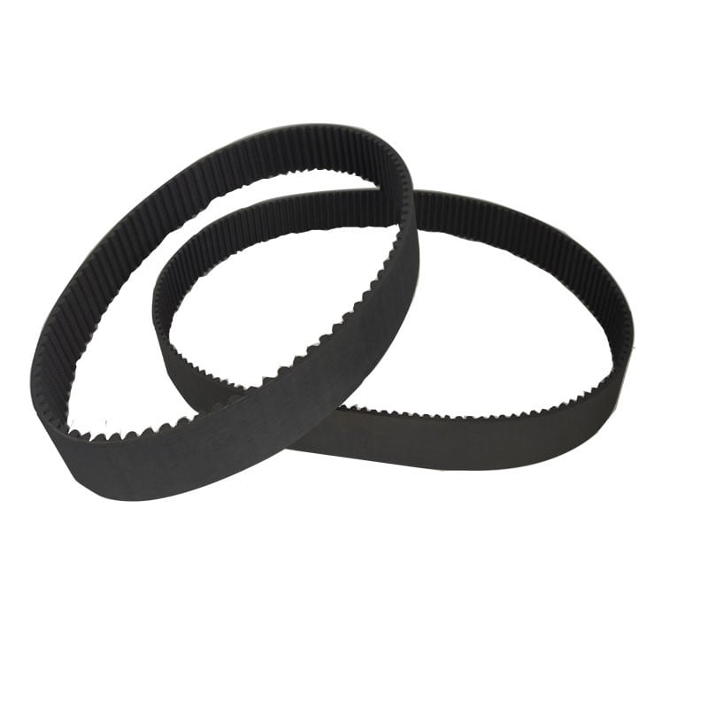
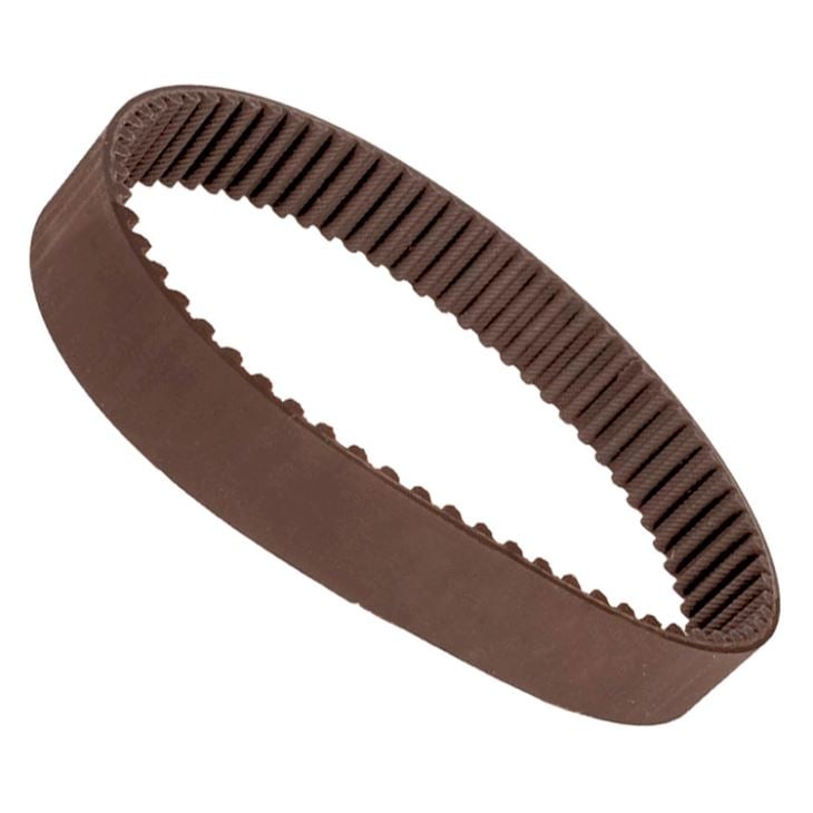
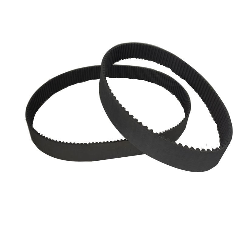
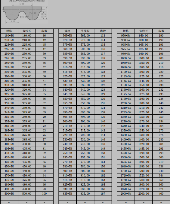
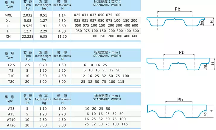
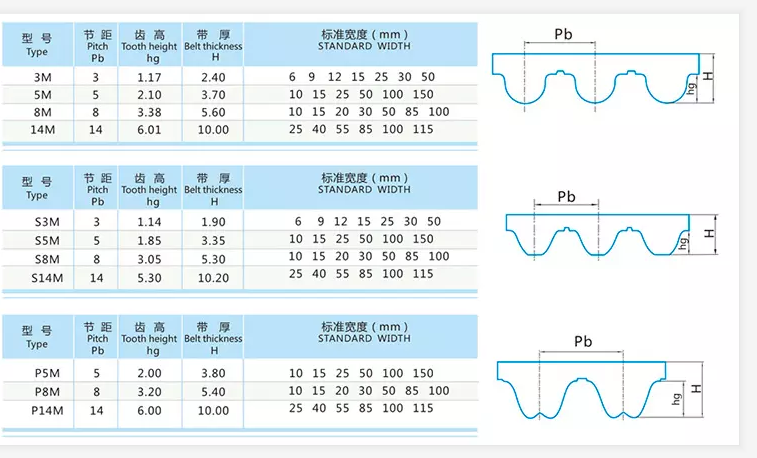
Best China manufacturer & factory China in Sendai Japan manufacturer CNC machine HTD 5M 180 36 teeth timing belt With high quality best price

EPG is one of the biggest manufacturers in China. We have advanced machines for production and new technology testing ability . Through adopting new technology from British, German, U.S.A, our products are best sellers all over European, America, and Southeast Asia.
Overview
Quick Details
- Applicable Industries:
-
Building Material Shops, Manufacturing Plant, Machinery Repair Shops, Food & Beverage Factory, farms, Energy & Mining
- Product name:
-
Timing belt
- Color:
-
Black
- Application:
-
Power Transmission Belt
- Size:
-
Standard Size
- Feature:
-
Low Noisy
- Quality:
-
High Level
- Packing:
-
Cartons
- Pitch:
-
5mm
- Advantage:
-
High performance
- Teeth:
-
36-400
Supply Ability
- Supply Ability:
- 5000 Piece/Pieces per Month
Packaging & Delivery
- Packaging Details
- Carton box+ wooden case
- Port
- Tianjin/Shanghai/Ningbo
-
Lead Time
: -
Quantity(Bags) 1 – 100 >100 Est. Time(days) 15 To be negotiated
Online Customization
EPG offer widest range of gearbox and speed reducers, conveyor chains and transmission parts like gear, sprocket, racks, pulley, shaves and taper bushes etc for various applications
Product Description
|
Product name |
Timing belt |
||||||
|
Material |
Rubber,PU, steel wire |
||||||
|
Type |
Open,round |
||||||
|
Model size |
T type:MXL,XL,L,H,XH,T2.5,T5,T10,T20,AT5,AT10,AT20 |
||||||
|
Arc type:2M,3M,5M,8M,14M,20M,S2M,S3M,44.5M,S5M,S8MS14M |
|||||||
|
Color |
Black,white,green,ect |
||||||
|
original place |
China |
||||||
|
Advantage |
High strength, anti oil, heat, aging,Good bending resistant performance |
||||||
|
Feature |
1. Polyurethane Open Ended Timing belt—-infinite long or joined endless type. |
||||||
|
Application |
belt widely used in machine tools, textile, printing, food packaging, wire and cable, instruments and meters, petroleum chemical, |
||||||
Different type timing belt
ARC type
T type
Open type
Round type
Application
Catalog
Payment
Our Company
HangZhou EPG – The biggest transmission parts manufacuturer in China Electrical Equipment Co.,Ltd was founded in HangZhou in 2008 and is a professional manufacturer and exporter that is concerned with the design, development and production.With detailed requirments, we can also develop your special designed product. Our product range includes all kinds of helical gear, spur gear, bevel gear, gear rack, worm gear, sprockets,chains, bearings.Keeping in mind that good service is the key to cooperating with clients, we strive to meet high quality standards, offer competitive prices and ensure prompt delivery. In this way, our products have continued to gain market acceptance and customers satisfaction over the past few years. We are aiming to meet the demands of the clienOur PTO drive shafts enable the user easy maintenance. The greasing nipples on standard crosses are positioned under angle to enable the user better access. Easier access is also possible because of the flexible cone. We listened to the wishes of our customers and placed the greasing nipple at wide-angle PTO’s into the cross bearing. The other novelty, we introduced with wide-angle PTO drive shafts is in line greasing. We wanted to additionally simplify the maintenance and extend the lifespan of joints.ts around the world..If you are interested in any of our products or would like to discuss a potential order, please feel free to contact us. We are looking forward to developing successful business relationships with new clients around the world in the future.
· Our Principle: “Credibility Supremacy, and Customer First”
· Our Promise: “High quality products, and Excellent Service”
· Our Value: “Being Honesty, Doing the Best, and Long-lasting Development”
· Our Aim: “Develop to be a leader in the power transmission parts industry in the world”
EPG – The biggest transmission parts manufacuturer in China Main Products
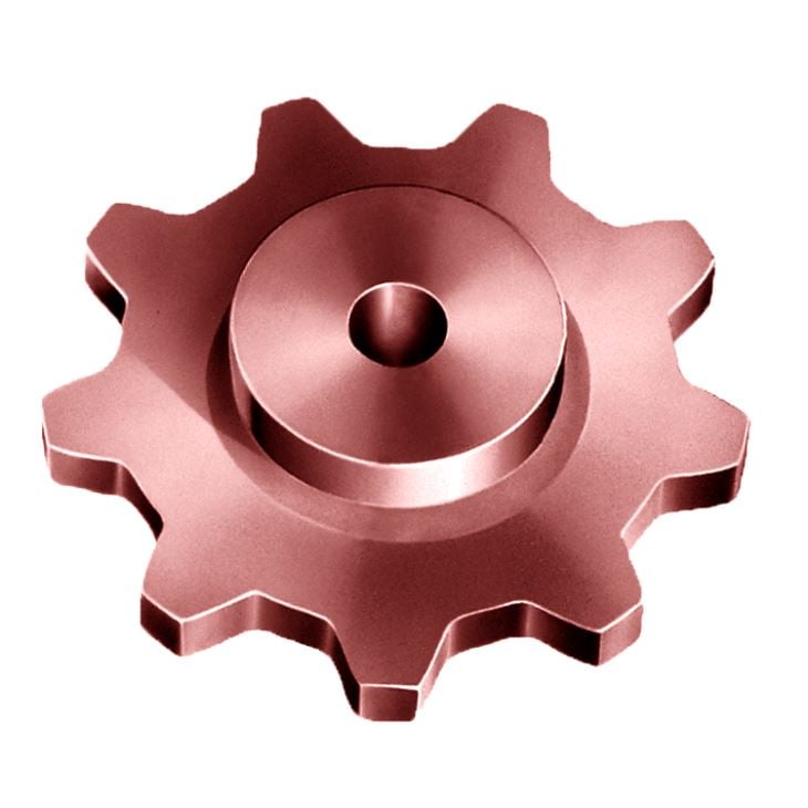
Industrial Sprocket
Motorcycle Sprocket
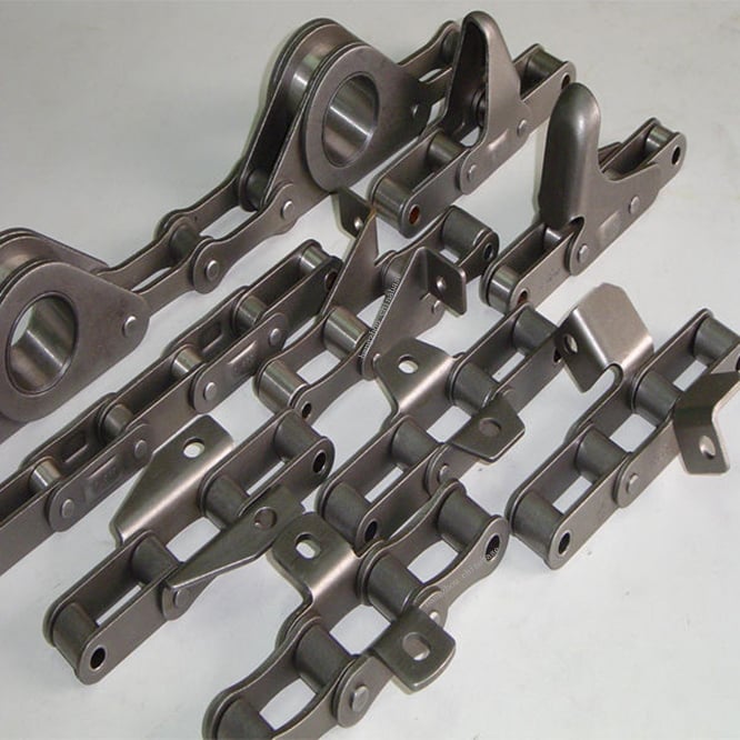
Roller Chain
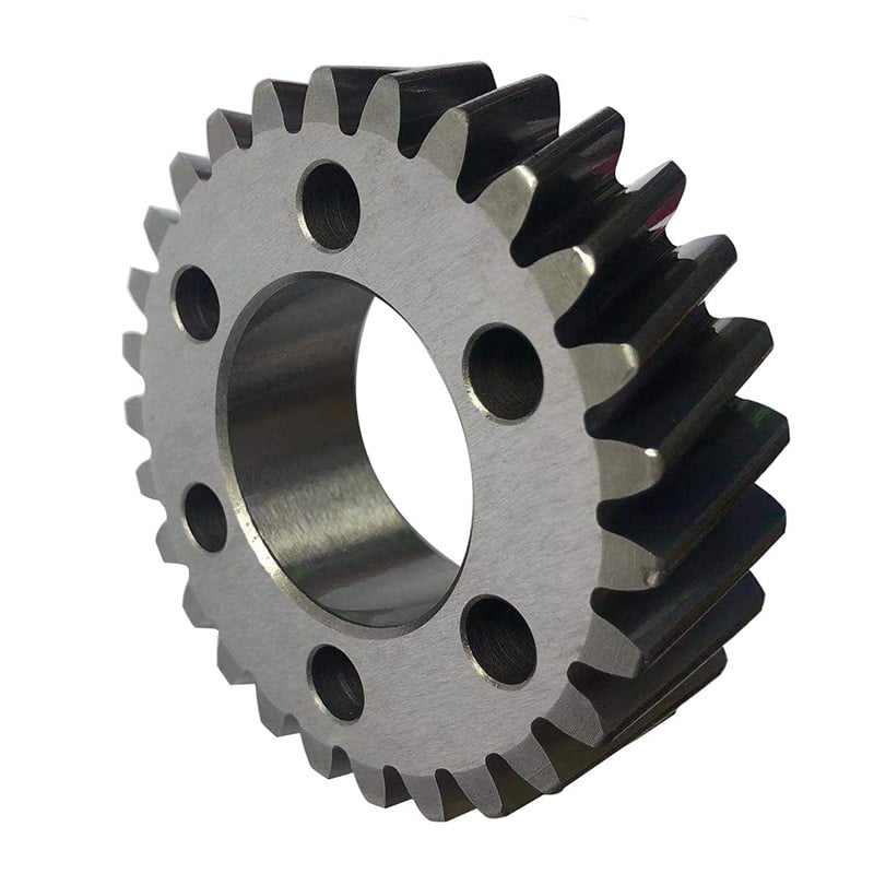
Spur Gear
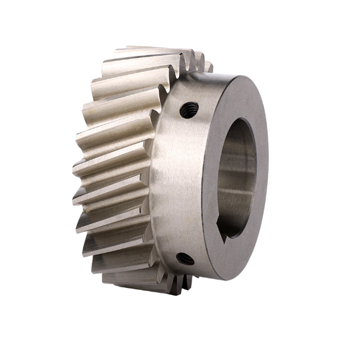
Our company has solid economic strength, builds the needs and requirements of our customers – from standard solutions to customer-specific designs.up a technician team contingent with high quality, possesses the production assembly line of technicalization in China and perfect system checking on product quality and runs marketing networks throughout the country. Helical Gear
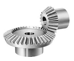
Bevel Gear
Plastic/POM/Nylon Gear
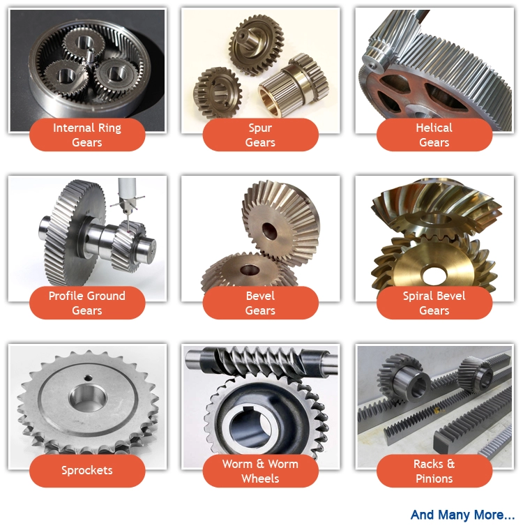
Small Pinion Gear
Worm Gear and shaft
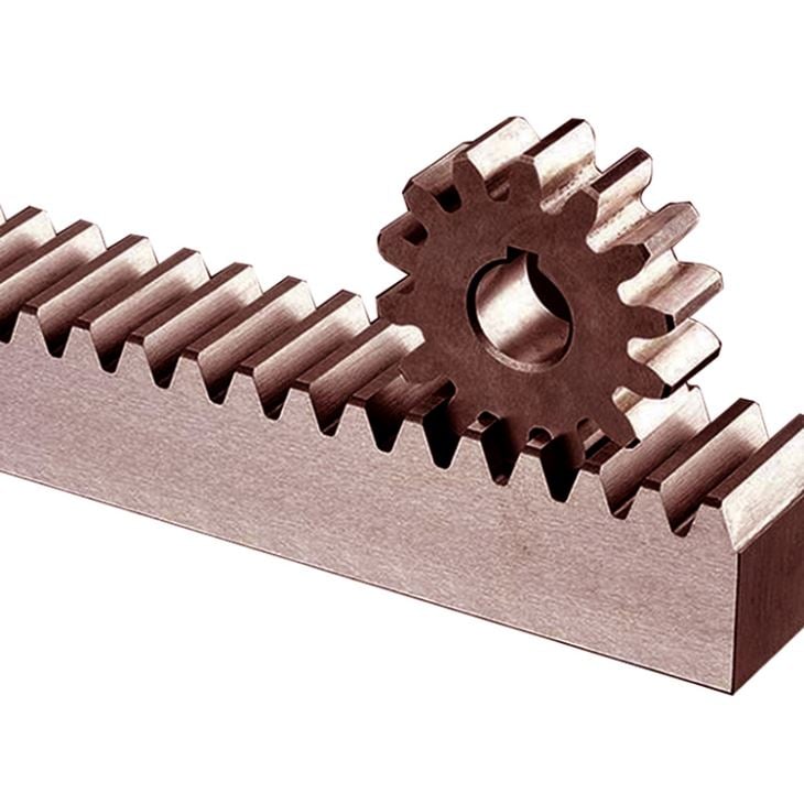
Gear Rack
Timing Pulley
Taper Bushing
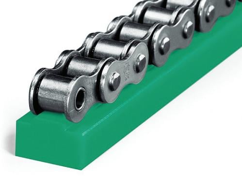
Chain Guides
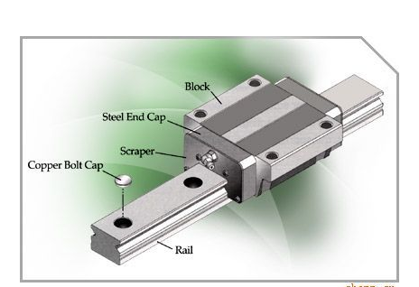
Linear Rail and Block
Ball Screw


Best China manufacturer & factory Supply customized OEM precision cnc casting spare parts china embroidery machine spare parts With high quality best price

We are aiming to meet the demands of the clients around the world.. a specialized supplier of a full range of chains, sprockets, gears, Gear-reducer inefficiency converts power to heat. AGMA ( American Gear Manufacturers Assn.) guidelines for worm-gear, helical, and other types of reducers limit the maximum allowable operating temperature to 100°F above ambient, not to exceed 200°F. To stay within these guidelines, worm-gear reducers must be considerably larger than equivalent-rated helical reducers (to dissipate more heat) or rely on auxiliary cooling devices.gear racks, V-belts, couplings and reducers, pto shaft, agricultural gearboxes….
Overview
Quick Details
- Applicable Industries:
-
Manufacturing Plant
- Brand Name:
-
OEM
- OEM Service:
-
Support
- Tolerance:
-
0.01-0.05mm or Customized
- Certification:
-
ISO9001, SGS
- Surface Treatment:
-
Sandblasting,Polishing,Anodize, Zinc,Nickel,Chrome,Plating, etc.
- Application:
-
Single direction FREE WHEEL (RA) Single direction PAWL torque limiter (SW) Disc torque limiter clutch with spring (FFT)
Automobile,Medical Equipments,Electric Appliance,Hardware,etc.
- Dimension:
-
As Customers’ Request
- Equipment:
-
Milling/Lathe/Drilling/Four/Three Axis CNC Machining Center
EPG specializing in the manufacture of rotocultivator ploughshares and other non-standardized farm machinery cutting tools.
- Drawing Format:
-
PRO/E, Auto CAD, Solid Works,IGS,UG, CAD/CAM/CAE
Supply Ability
- Supply Ability:
- 10000 Piece/Pieces per Month
Packaging & Delivery
- Port
- nb
-
Lead Time
: -
Quantity(Pieces) 1 – 500 >500 Est. Time(days) 30 To be negotiated
Online Customization
Supply customized OEM precision cnc casting spare parts china embroidery machine spare parts
Product Description
| Product Type | CNC turning, milling, drilling, grinding, wire EDM cutting etc. |
| Our Services | CNC Machining,Plastic Injection,Stamping,Die Casting,Silicone And Rubber,Aluminum Extrusion,Mould Making,etc |
| Material | Aluminum,Brass,Stainless Steel,Copper,Plastic,Wood,Silicone,Rubber,Or as per the customers’ requirements |
| Surface Treatment |
Anodizing,Sandblasting,Painting,Powder coating,Plating,Silk Printing,Brushing,Polishing,Laser Engraving |
| Dimension | As customers’ request |
| Service Project | To provide production design, production and technical service, mould development and processing, etc |
| Drawing Format: | PRO/E, Auto CAD, Solid Works,IGS,UG, CAD/CAM/CAE |
| Testing Machine | Digital Height Gauge, caliper, Coordinate measuring machine, projection machine, roughness tester, hardness tester and so on |
| Industry used | Machinery; heavy duty equipment; electronic device; Auto spare parts; optical telecommunication |
| Packing | Eco-friendly pp bag / EPE Foam /Carton boxes or wooden boxes As customer’s specific requirements |
| Trial sample time | 7-10 days after confirmation |
| Delivery time | 7-30 days after receive the pre-payments |
| Payment Terms | T/T,Western Union,Paypal |
OEM Service
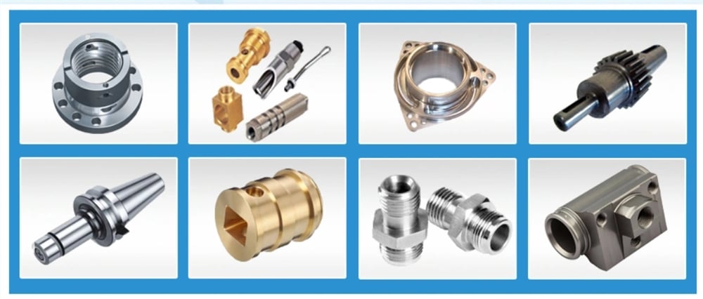
OEM Parts
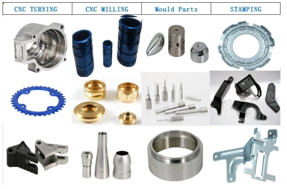
Surface Treatment
Production Process
Why Us