Product Description
OEM transmission Hard Chrome Forging Casting steel 45C Carbon Steel Transmission Spur Helical Pinion Spline Gear Shaft propeller shaft
|
FULL SPLINED SHAFT |
|||
|
PART No. |
DESCRIPTION |
SPLINE SIZE |
LENGTH |
|
B283 |
Splined shafting 1045 carbon steel |
1 3/8″ dia x 6 spline |
10″ (250mm) |
|
B6283 |
1 3/8″ dia x 6 spline |
29 1/2″ (750mm) |
|
|
B7283 |
1 3/8″ dia x 6 spline |
9.8ft (3 mtrs) |
|
|
B2657 |
1 3/8″ dia x 21 spline |
10″ (250mm) |
|
|
B7657 |
1 3/4 dia x 20 spline |
10″ (250mm) |
|
|
B9657 |
1 3/4 dia x 20 spline |
39″ (1000mm) |
|
|
B8283 |
Heat treated high tensile grade 8 |
1 3/8″ dia x 6 spline |
10″ (250mm) |
|
B8657 |
1 3/4″ dia x 20 spline |
10″ (250mm) |
|
|
SPLINED SHAFT – PLAIN CENTRE |
|||
|
PART No |
DESCRIPTION |
SPLINE SIZE |
LENGTH |
|
B8284 |
Plain Centre |
1 3/8″ dia x 6 spline |
10″ (250mm) |
|
B8658 |
1 3/4″ dia x 20 spline |
||
|
PART No. |
DESCRIPTION |
O.D. |
SPLINE SIZE |
LENGTH |
|
B287 |
Splined sleeve |
2 1/8 ” (54mm) |
1 3/8″ x 6 spline |
3 1/4″ (82mm) |
|
B7287 |
2 1/8 ” (54mm) |
1 3/8″ x 6 spline |
6″ (150mm) |
|
|
B2418 |
2 1/8 ” (54mm) |
1 3/4″ x 21 spline |
6″ (150mm) |
|
|
B6418 |
|
1 3/4″ x 20 spline |
6″ (150mm) |
|
|
B8287 |
Heat treated high tensile grade 8 |
2 1/8 ” (54mm) |
1 3/8 x 6 spline |
6″ (150mm) |
|
B9418 |
3″ (75mm) |
1 3/4″ x 20 spline |
Heavy wall 6″ (150mm) |
Application
Company Profile
/* March 10, 2571 17:59:20 */!function(){function s(e,r){var a,o={};try{e&&e.split(“,”).forEach(function(e,t){e&&(a=e.match(/(.*?):(.*)$/))&&1
| Material: | Alloy Steel |
|---|---|
| Load: | Drive Shaft |
| Stiffness & Flexibility: | Flexible Shaft |
| Journal Diameter Dimensional Accuracy: | IT6-IT9 |
| Axis Shape: | Straight Shaft |
| Shaft Shape: | Real Axis |
| Samples: |
US$ 9999/Piece
1 Piece(Min.Order) | |
|---|

How do spline shafts handle variations in torque and rotational force?
Spline shafts are designed to handle variations in torque and rotational force in mechanical systems. Here’s a detailed explanation:
1. Interlocking Splines:
Spline shafts have a series of interlocking splines along their length. These splines engage with corresponding splines on the mating component, such as gears or couplings. The interlocking design ensures a secure and robust connection, capable of transmitting torque and rotational force.
2. Load Distribution:
When torque is applied to a spline shaft, the load is distributed across the entire engagement surface of the splines. This helps to minimize stress concentrations and prevents localized wear or failure. The load distribution capability of spline shafts allows them to handle variations in torque and rotational force effectively.
3. Material Selection:
Spline shafts are typically made from materials with high strength and durability, such as alloy steels. The material selection is crucial in handling variations in torque and rotational force. It ensures that the spline shaft can withstand the applied loads without deformation or failure.
4. Spline Profile:
The design of the spline profile also contributes to the handling of torque variations. The spline profile determines the contact area and the distribution of forces along the splines. By optimizing the spline profile, manufacturers can enhance the load-carrying capacity and improve the ability of the spline shaft to handle variations in torque.
5. Surface Finish and Lubrication:
Proper surface finish and lubrication play a crucial role in the performance of spline shafts. A smooth surface finish reduces friction and wear, while suitable lubrication minimizes heat generation and ensures smooth operation. These factors help in handling variations in torque and rotational force by reducing the impact of friction and wear on the spline engagement.
6. Design Considerations:
Engineers take several design considerations into account to ensure spline shafts can handle variations in torque and rotational force. These considerations include appropriate spline dimensions, tooth profile geometry, spline fit tolerance, and the selection of mating components. By carefully designing the spline shaft and its mating components, engineers can optimize the system’s performance and reliability.
7. Overload Protection:
In some applications, spline shafts may be equipped with overload protection mechanisms. These mechanisms, such as shear pins or torque limiters, are designed to disconnect the drive temporarily or slip when the torque exceeds a certain threshold. This protects the spline shaft and other components from damage due to excessive torque.
Overall, spline shafts handle variations in torque and rotational force through their interlocking splines, load distribution capability, appropriate material selection, optimized spline profiles, surface finish, lubrication, design considerations, and, in some cases, overload protection mechanisms. These features ensure efficient torque transmission and enable spline shafts to withstand the demands of various mechanical systems.

Can spline shafts be used in automotive applications, and if so, how?
Yes, spline shafts are extensively used in automotive applications due to their ability to transmit torque and provide reliable power transmission. Here’s how spline shafts are used in automotive applications:
Spline shafts play a crucial role in various automotive systems and components, including:
- Drivetrain: Spline shafts are an integral part of the drivetrain system in vehicles. They transmit torque from the engine to the wheels, allowing the vehicle to move. Spline shafts are present in components such as the transmission, differential, and axle shafts. In manual transmissions, the spline shaft connects the transmission input shaft to the clutch disc, enabling power transfer from the engine. In automatic transmissions, spline shafts are used in the torque converter and the output shaft.
- Steering System: Spline shafts are employed in the steering system to transmit torque from the steering wheel to the steering rack or gearbox. They provide a direct connection between the driver’s input and the movement of the wheels, allowing for steering control.
- Power Take-Off (PTO) Systems: Some vehicles, particularly commercial trucks and agricultural machinery, utilize PTO systems. Spline shafts are used in PTOs to transfer power from the vehicle’s engine to auxiliary equipment, such as hydraulic pumps, generators, or agricultural implements.
- Transfer Cases: In four-wheel-drive (4WD) or all-wheel-drive (AWD) vehicles, transfer cases are used to distribute power to the front and rear axles. Spline shafts are utilized in the transfer case to transfer torque between the transmission and the front and rear drive shafts.
- Propeller Shafts: Spline shafts are present in propeller shafts, which transmit torque from the transmission or transfer case to the rear axle in rear-wheel-drive vehicles. They accommodate the relative movement between the transmission and the axle due to suspension travel.
In automotive applications, spline shafts are designed to withstand high torque loads, provide precise torque transmission, and accommodate misalignments and fluctuations in operating conditions. They are typically made from high-strength steel or alloy materials to ensure durability and resistance to wear. Proper lubrication is essential to minimize friction and ensure smooth operation.
The use of spline shafts in automotive applications allows for efficient power transmission, precise control, and reliable performance, contributing to the overall functionality and drivability of vehicles.

Can you explain the common applications of spline shafts in machinery?
Spline shafts have various common applications in machinery where torque transmission, relative movement, and load distribution are essential. Here’s a detailed explanation:
1. Gearboxes and Transmissions:
Spline shafts are commonly used in gearboxes and transmissions where they facilitate the transmission of torque from the input shaft to the output shaft. The splines on the shaft engage with corresponding splines on the gears, allowing for precise torque transfer and accommodating relative movement between the gears.
2. Power Take-Off (PTO) Units:
In agricultural and industrial machinery, spline shafts are employed in power take-off (PTO) units. PTO units allow the transfer of power from the engine to auxiliary equipment, such as pumps, generators, or farm implements. Spline shafts enable the torque transfer and accommodate the relative movement required for PTO operation.
3. Steering Systems:
Spline shafts play a crucial role in steering systems, especially in vehicles. They are used in steering columns to transmit torque from the steering wheel to the steering rack or gearbox. The splines on the shaft ensure precise torque transfer while allowing for the axial movement required for steering wheel adjustment.
4. Machine Tools:
Spline shafts find applications in machine tools such as milling machines, lathes, and grinding machines. They are used to transmit torque and enable the relative movement required for tool positioning, feed control, and spindle rotation. Spline shafts ensure accurate and controlled movement of the machine tool components.
5. Industrial Pumps and Compressors:
Spline shafts are utilized in various types of pumps and compressors, including centrifugal pumps, gear pumps, and reciprocating compressors. They transmit torque from the driver (such as an electric motor or an engine) to the impeller or rotor, enabling fluid or gas transfer. Spline shafts accommodate the axial or radial movement caused by thermal expansion or misalignment.
6. Printing and Packaging Machinery:
Spline shafts are integral components in printing and packaging machinery. They are used in processes such as web handling, where precise torque transmission and relative movement are required for tasks like tension control, registration, and material feeding. Spline shafts ensure accurate and synchronized movement of the printing and packaging elements.
7. Aerospace and Defense Systems:
In the aerospace and defense industries, spline shafts are utilized in various applications, including aircraft landing gear systems, missile guidance systems, and helicopter rotor systems. They enable torque transmission, accommodate relative movement, and ensure precise control in critical aerospace and defense mechanisms.
8. Construction and Earthmoving Equipment:
Spline shafts are employed in construction and earthmoving equipment, such as excavators, bulldozers, and loaders. They are used in hydraulic systems to transmit torque from the hydraulic motor to the driven components, such as the digger arm or the bucket. Spline shafts enable efficient power transfer and allow for the articulation and movement of the equipment.
These are just a few examples of the common applications of spline shafts in machinery. Their versatility, torque transmission capabilities, and ability to accommodate relative movement make them essential components in various industries where precise power transfer and flexibility are required.


editor by CX 2024-02-08
China factory Manufacturer Direct Drive Spur Gear Helical Gear Spline Gear Shaft
Product Description
Product Description
Product Parameters
| Item | Spur Gear Axle Shaft |
| Material | 4140,4340,40Cr,42Crmo,42Crmo4,20Cr,20CrMnti, 20Crmo,35Crmo |
| OEM NO | Customize |
| Certification | ISO/TS16949 |
| Test Requirement | Magnetic Powder Test, Hardness Test, Dimension Test |
| Color | Paint , Natural Finish ,Machining All Around |
| Material | Aluminum: 5000series(5052…)/6000series(6061…)/7000series(7075…) |
| Steel: Carbon Steel,Middle Steel,Steel Alloy,etc. | |
| Stainess Steel: 303/304/316,etc. | |
| Copper/Brass/Bronze/Red Copper,etc. | |
| Plastic:ABS,PP,PC,Nylon,Delrin(POM),Bakelite,etc. | |
| Size | According to Customer’s drawing or samples |
| Process | CNC machining,Turning,Milling,Stamping,Grinding,Welding,Wire Injection,Cutting,etc. |
| Tolerance | ≥+/-0.03mm |
| Surface Treatment | (Sandblast)&(Hard)&(Color)Anodizing,(Chrome,Nickel,Zinc…)Plating,Painting,Powder Coating,Polishing,Blackened,Hardened,Lasering,Engraving,etc. |
| File Formats | ProE,SolidWorks,UG,CAD,PDF(IGS,X-T,STP,STL) |
| Sample | Available |
| Packing | Spline protect cover ,Wood box ,Waterproof membrane; Or per customers’ requirements. |
Our Advantages
Why Choose US ???
1. Equipment :
Our company boasts all necessary production equipment,
including Hydraulic press machines, Japanese CNC lathe (TAKISAWA), Korean gear hobbing machine (I SNT), gear shaping machine, machining center, CNC grinder, heat treatment line etc.
2. Processing precision:
We are a professional gear & gear shafts manufacturer. Our gears are around 6-7 grade in mass production.
3. Company:
We have 90 employees, including 10 technical staffs. Covering an area of 20000 square meters.
4. Certification :
Oue company has passed ISO 14001 and TS16949
5.Sample service :
We provide free sample for confirmation and customer bears the freight charges
6.OEM service :
Having our own factory and professional technicians,we welcome OEM orders as well.We can design and produce the specific product you need according to your detail information
Cooperation Partner
Company Profile
Our Featured Products
/* March 10, 2571 17:59:20 */!function(){function s(e,r){var a,o={};try{e&&e.split(“,”).forEach(function(e,t){e&&(a=e.match(/(.*?):(.*)$/))&&1
| Material: | Alloy Steel |
|---|---|
| Load: | Drive Shaft |
| Axis Shape: | Straight Shaft |
| Appearance Shape: | Round |
| Rotation: | Cw |
| Yield: | 5, 000PCS / Month |
| Samples: |
US$ 0/Piece
1 Piece(Min.Order) | |
|---|
| Customization: |
Available
| Customized Request |
|---|

How does the design of a spline shaft affect its performance?
The design of a spline shaft plays a crucial role in determining its performance characteristics. Here’s a detailed explanation:
1. Torque Transmission:
The design of the spline shaft directly affects its ability to transmit torque efficiently. Factors such as the spline profile, number of splines, and engagement length influence the torque-carrying capacity of the shaft. A well-designed spline profile with optimized dimensions ensures maximum contact area and load distribution, resulting in improved torque transmission.
2. Load Distribution:
A properly designed spline shaft distributes the applied load evenly across the engagement surfaces. This helps to minimize stress concentrations and prevents localized wear or failure. The design should consider factors such as spline profile geometry, tooth form, and surface finish to achieve optimal load distribution and enhance the overall performance of the shaft.
3. Misalignment Compensation:
Spline shafts can accommodate a certain degree of misalignment between the mating components. The design of the spline profile can incorporate features that allow for angular or parallel misalignment, ensuring effective power transmission even under misaligned conditions. Proper design considerations help maintain smooth operation and prevent excessive stress or premature failure.
4. Torsional Stiffness:
The design of the spline shaft influences its torsional stiffness, which is the resistance to twisting under torque. A stiffer shaft design reduces torsional deflection, improves torque response, and enhances the system’s overall performance. The shaft material, diameter, and spline profile all contribute to achieving the desired torsional stiffness.
5. Fatigue Resistance:
The design of the spline shaft should consider fatigue resistance to ensure long-term durability. Fatigue failure can occur due to repeated or cyclic loading. Proper design practices, such as optimizing the spline profile, selecting appropriate materials, and incorporating suitable surface treatments, can enhance the fatigue resistance of the shaft and extend its service life.
6. Surface Finish and Lubrication:
The surface finish of the spline shaft and the lubrication used significantly impact its performance. A smooth surface finish reduces friction, wear, and the potential for corrosion. Proper lubrication ensures adequate film formation, reduces heat generation, and minimizes wear. The design should incorporate considerations for surface finish requirements and lubrication provisions to optimize the shaft’s performance.
7. Environmental Considerations:
The design should take into account the specific environmental conditions in which the spline shaft will operate. Factors such as temperature, humidity, exposure to chemicals, or abrasive particles can affect the shaft’s performance and longevity. Suitable material selection, surface treatments, and sealing mechanisms can be incorporated into the design to withstand the environmental challenges.
8. Manufacturing Feasibility:
The design of the spline shaft should also consider manufacturing feasibility and cost-effectiveness. Complex designs may be challenging to produce or require specialized manufacturing processes, resulting in increased production costs. Balancing design complexity with manufacturability is crucial to ensure a practical and efficient manufacturing process.
By considering these design factors, engineers can optimize the performance of spline shafts, resulting in enhanced torque transmission, improved load distribution, misalignment compensation, torsional stiffness, fatigue resistance, surface finish, and environmental compatibility. A well-designed spline shaft contributes to the overall efficiency, reliability, and longevity of the mechanical system in which it is used.
How do spline shafts contribute to precise and consistent rotation?
Spline shafts play a crucial role in achieving precise and consistent rotation in mechanical systems. Here’s how spline shafts contribute to these characteristics:
1. Interlocking Design:
Spline shafts feature a series of ridges or teeth, known as splines, that interlock with corresponding grooves or slots in mating components. This interlocking design ensures a positive connection between the shaft and the mating part, allowing for precise and consistent rotation. The engagement between the splines provides resistance to axial and radial movement, minimizing play or backlash that can introduce inaccuracies in rotation.
2. Load Distribution:
The interlocking engagement of spline shafts allows for effective load distribution along the length of the shaft. This helps distribute the applied torque evenly, reducing stress concentrations and minimizing the risk of localized deformation or failure. By distributing the load, spline shafts contribute to consistent rotation and prevent excessive wear on specific areas of the shaft or the mating components.
3. Torque Transmission:
Spline shafts are specifically designed to transmit torque efficiently from one component to another. The close fit between the splines ensures a high torque-carrying capacity, enabling the shaft to transfer rotational force without significant power loss. This efficient torque transmission contributes to precise and consistent rotation, allowing for accurate positioning and motion control in various applications.
4. Rigidity and Stiffness:
Spline shafts are typically constructed from materials with high rigidity and stiffness, such as steel or alloy. This inherent rigidity helps maintain the dimensional integrity of the shaft and minimizes deflection or bending under load. By providing a stable and stiff rotational axis, spline shafts contribute to precise and consistent rotation, particularly in applications that require tight tolerances or high-speed operation.
5. Alignment and Centering:
The interlocking nature of spline shafts aids in the alignment and centering of rotating components. The splines ensure proper positioning and orientation of the shaft relative to the mating part, facilitating concentric rotation. This alignment helps prevent wobbling, vibrations, and eccentricity, which can adversely affect rotation accuracy and consistency.
6. Lubrication and Wear Reduction:
Proper lubrication of spline shafts is essential for maintaining precise and consistent rotation. Lubricants reduce friction between the mating surfaces, minimizing wear and preventing stick-slip phenomena that can cause irregular rotation. The use of lubrication also helps dissipate heat generated during operation, ensuring optimal performance and longevity of the spline shaft.
By incorporating interlocking design, load distribution, efficient torque transmission, rigidity, alignment, and lubrication, spline shafts contribute to precise and consistent rotation in mechanical systems. Their reliable and accurate rotational characteristics make them suitable for a wide range of applications, from automotive and aerospace to machinery and robotics.

In which industries are spline shafts typically used?
Spline shafts find applications in a wide range of industries where torque transmission, relative movement, and load distribution are critical. Here’s a detailed explanation:
1. Automotive Industry:
The automotive industry extensively uses spline shafts in various components and systems. They are found in transmissions, drivelines, steering systems, differentials, and axle assemblies. Spline shafts enable the transmission of torque, accommodate relative movement, and ensure efficient power transfer in vehicles.
2. Aerospace and Defense Industry:
Spline shafts are essential in the aerospace and defense industry. They are used in aircraft landing gear systems, actuation mechanisms, missile guidance systems, engine components, and rotor assemblies. The aerospace and defense sector relies on spline shafts for precise torque transfer, relative movement accommodation, and critical control mechanisms.
3. Industrial Machinery and Equipment:
Spline shafts are widely employed in industrial machinery and equipment. They are used in gearboxes, machine tools, pumps, compressors, conveyors, printing machinery, and packaging equipment. Spline shafts enable torque transmission, accommodate misalignments and vibrations, and ensure accurate movement and synchronization of machine components.
4. Agriculture and Farming:
The agriculture and farming industry extensively uses spline shafts in equipment such as tractors, harvesters, and agricultural implements. Spline shafts are found in power take-off (PTO) units, transmission systems, hydraulic mechanisms, and steering systems. They enable torque transfer, accommodate relative movement, and provide flexibility in agricultural machinery.
5. Construction and Mining:
In the construction and mining industries, spline shafts are used in equipment such as excavators, loaders, bulldozers, and drilling rigs. They are found in hydraulic systems, power transmission systems, and articulated mechanisms. Spline shafts facilitate torque transmission, accommodate misalignments, and enable efficient power transfer in heavy-duty machinery.
6. Marine and Offshore:
Spline shafts have applications in the marine and offshore industry. They are used in propulsion systems, thrusters, rudders, winches, and marine pumps. Spline shafts enable torque transmission in marine vessels and offshore equipment, accommodating axial and radial movement, and ensuring reliable power transfer.
7. Energy and Power Generation:
Spline shafts are utilized in the energy and power generation sector. They are found in turbines, generators, compressors, and other rotating equipment. Spline shafts enable torque transmission and accommodate relative movement in power generation systems, ensuring efficient and reliable operation.
8. Rail and Transportation:
Spline shafts are employed in the rail and transportation industry. They are found in locomotives, railcar systems, and suspension mechanisms. Spline shafts enable torque transfer, accommodate movement and vibrations, and ensure precise control in rail and transportation applications.
These are just a few examples of the industries where spline shafts are typically used. Their versatility, torque transmission capabilities, and ability to accommodate relative movement make them vital components in various sectors that rely on efficient power transfer, flexibility, and precise control.
editor by CX 2024-02-07
China factory Factory Hard Chrome 42CrMo Forging Steel Transmission Main Spur Helical Pinion Spline Gear Shaft
Product Description
Forging shaft/spindle/roll/roller/axle
Product Disply
Inspection
| Specification | customer’s drawings |
| Material | cast iron, Grey iron, ductile iron, carbon steel, low alloy steel, tool steel, steel, stainless steel, brass, copper, aluminum alloy, zinc etc |
| Process | Sand casting,Coated sand casting,Shell mold casting,Lost foam casting ,V- process,Centrifugal casting,Ceramic Casting,machining,free forging,die forging,pressure forming ,roll forging,precision forging,etc. |
| casting | sand casting,precision casting,centrifugal casting,lost foam casting,die casting,gravity casting |
| machine | lathe,CNC,drilling machine,milling machine,boring machine,planting machine,machining center etc |
| Application | Automobile, agricultural machinery, furniture, construction, home appliances, electronics. |
| surface treatment | powder coating,painting,spraying,electric galvanization,coating,zinc phosphide,impregnation,painting,spray paint,black and blue oxide coating, |
| Inspection equipment | Profile projector,Rockwell hardness tester,Vickers hardness tester roughness tester,air gage,concentricity tester,universial microscope,CMM,digital caliper and etc. |
| Production Usage | Auto parts,train parts,mining accessories,engineering machinery parts,valves,pipe fittings,construction machinery and furniture accessories,agricultural machinery parts |
| Remark | (1)Any RFQ, Please feel free to send your drawings(CAD/PDF)for your quotation. (2)All parts are not in stock, customized only! |
FAQ
Q: What do I need for offering a quote ?
A: Please offer us 2D or 3D drawings (with material, dimension, tolerance, surface treatment and other technical requirement etc.) ,quantity, application or samples. Then we will quote the best price within 24h.
Q: What is your MOQ?
A: MOQ depends on our client’s needs, besides,we welcome trial order before mass-production.
Q: What is the production cycle?
A: It varies a lot depending on product dimension,technical requirements and quantity. We always try to meet customers’ requirement by adjusting our workshop schedule.
Q: What kind of payment terms do you accept?
A.: T/T, L/C, Escrow, Paypal, western union, etc.
Q: Is it possible to know how is my product going on without visiting your company?
A: We will offer a detailed products schedule and send weekly reports with digital pictures and videos which show the machining progress.
/* March 10, 2571 17:59:20 */!function(){function s(e,r){var a,o={};try{e&&e.split(“,”).forEach(function(e,t){e&&(a=e.match(/(.*?):(.*)$/))&&1
| Material: | Carbon Steel |
|---|---|
| Load: | Drive Shaft |
| Stiffness & Flexibility: | Stiffness / Rigid Axle |
| Journal Diameter Dimensional Accuracy: | IT6-IT9 |
| Axis Shape: | Straight Shaft |
| Shaft Shape: | Real Axis |
| Customization: |
Available
| Customized Request |
|---|

What safety considerations should be kept in mind when working with spline shafts?
Working with spline shafts requires adherence to certain safety considerations to ensure the well-being of personnel and the proper functioning of the machinery or equipment. Here’s a detailed explanation:
1. Personal Protective Equipment (PPE):
When working with spline shafts, individuals should wear appropriate personal protective equipment, including safety glasses, gloves, and protective clothing. PPE helps protect against potential hazards such as flying debris, sharp edges, or contact with lubricants.
2. Lockout/Tagout Procedures:
Prior to performing any maintenance or repair work on machinery or equipment involving spline shafts, proper lockout/tagout procedures should be followed. This involves isolating the power source, de-energizing the system, and securing it with lockout devices or tags to prevent accidental startup or release of stored energy.
3. Training and Competence:
Only trained and competent personnel should work with spline shafts. They should have a thorough understanding of the machinery or equipment, including the operation, maintenance, and safety procedures specific to spline shafts. Adequate training and knowledge help minimize the risk of accidents or improper handling.
4. Proper Handling and Lifting Techniques:
When moving or lifting machinery components that include spline shafts, proper techniques should be employed. This includes using appropriate lifting equipment, maintaining a stable posture, and avoiding sudden movements that could cause strain or injury.
5. Inspection and Maintenance:
Spline shafts should be regularly inspected for signs of wear, damage, or misalignment. Any abnormalities should be addressed promptly by qualified personnel. Routine maintenance, such as lubrication and cleaning, should be performed according to the manufacturer’s recommendations to ensure optimal performance and longevity.
6. Correct Installation and Alignment:
During installation or replacement of spline shafts, proper alignment and fit should be ensured. The shafts should be correctly seated and engaged with the mating components, following the manufacturer’s guidelines. Improper installation or misalignment can lead to premature wear, excessive stress, or failure of the spline shafts.
7. Hazardous Environments:
When spline shafts are used in hazardous environments, such as those with flammable substances, extreme temperatures, or high vibrations, additional safety measures may be required. These may include explosion-proof enclosures, temperature monitoring, or vibration damping systems.
8. Emergency Procedures:
Emergency procedures should be established and communicated to all personnel working with spline shafts. This includes knowing the location of emergency stops, emergency shutdown procedures, and the contact information for emergency response personnel.
9. Manufacturer’s Guidelines:
It is essential to follow the manufacturer’s guidelines and recommendations regarding the installation, operation, and maintenance of spline shafts. The manufacturer’s instructions provide specific safety information and precautions tailored to their product.
By taking these safety considerations into account and implementing appropriate measures, the risks associated with working with spline shafts can be minimized. Safety should always be a top priority when dealing with machinery or equipment that incorporates spline shafts.

How do spline shafts handle variations in load capacity and weight?
Spline shafts are designed to handle variations in load capacity and weight in mechanical systems. Here’s how they accomplish this:
1. Material Selection:
Spline shafts are typically made from high-strength materials such as steel or alloy, chosen for their ability to withstand heavy loads and provide durability. The selection of materials takes into account factors such as tensile strength, yield strength, and fatigue resistance to ensure the shaft can handle variations in load capacity and weight.
2. Engineering Design:
Spline shafts are designed with consideration for the anticipated loads and weights they will encounter. The dimensions, profile, and number of splines are determined based on the expected torque requirements and the magnitude of the applied loads. By carefully engineering the design, spline shafts can handle variations in load capacity and weight while maintaining structural integrity and reliable performance.
3. Load Distribution:
The interlocking engagement of spline shafts allows for effective load distribution along the length of the shaft. This helps distribute the applied loads evenly, preventing localized stress concentrations and minimizing the risk of deformation or failure. By distributing the load, spline shafts can handle variations in load capacity and weight without compromising their performance.
4. Structural Reinforcement:
In applications with higher load capacities or heavier weights, spline shafts may incorporate additional structural features to enhance their strength. This can include thicker spline teeth, larger spline diameters, or reinforced sections along the shaft. By reinforcing critical areas, spline shafts can handle increased loads and weights while maintaining their integrity.
5. Lubrication and Surface Treatment:
Proper lubrication is essential for spline shafts to handle variations in load capacity and weight. Lubricants reduce friction between the mating surfaces, minimizing wear and preventing premature failure. Additionally, surface treatments such as coatings or heat treatments can enhance the hardness and wear resistance of the spline shaft, improving its ability to handle varying loads and weights.
6. Testing and Validation:
Spline shafts undergo rigorous testing and validation to ensure they meet the specified load capacity and weight requirements. This may involve laboratory testing, simulation analysis, or field testing under real-world conditions. By subjecting spline shafts to thorough testing, manufacturers can verify their performance and ensure they can handle variations in load capacity and weight.
Overall, spline shafts are designed and engineered to handle variations in load capacity and weight by utilizing appropriate materials, optimizing the design, distributing loads effectively, incorporating structural reinforcement when necessary, implementing proper lubrication and surface treatments, and conducting thorough testing and validation. These measures enable spline shafts to reliably transmit torque and handle varying loads in diverse mechanical applications.

How does a spline shaft differ from other types of shafts?
A spline shaft differs from other types of shafts in several ways. Here’s a detailed explanation:
1. Spline Structure:
A spline shaft features a series of ridges or teeth (splines) that are machined onto its surface. These splines create a precise and controlled interface with mating components, allowing for torque transmission and relative movement. In contrast, other types of shafts, such as plain shafts or keyed shafts, do not have the splines and rely on different mechanisms for torque transmission.
2. Torque Transmission and Relative Movement:
Unlike plain shafts or keyed shafts, which transmit torque through a frictional or mechanical connection, spline shafts allow for both torque transmission and relative movement between the shaft and mating components. The splines on the shaft engage with corresponding splines on the mating component, creating an interlock that transfers rotational force while accommodating axial or radial displacement. This feature provides flexibility and is particularly useful in applications where misalignment or relative movement needs to be accommodated.
3. Load Distribution:
One of the advantages of spline shafts is their ability to distribute loads over a larger surface area. The multiple contact points created by the splines help distribute the applied load evenly along the shaft’s length. This load distribution minimizes stress concentrations and reduces the risk of premature wear or failure. In contrast, other types of shafts may rely on a single keyway or frictional contact, which can result in higher stress concentrations and limited load distribution.
4. Design Flexibility:
Spline shafts offer greater design flexibility compared to other types of shafts. The number, size, and shape of the splines can be customized to meet specific design requirements. This allows for optimization of torque transmission, load-bearing capacity, and relative movement characteristics based on the application’s needs. Other types of shafts may have more standardized designs and limited customization options.
5. Application Variability:
Spline shafts find widespread use in various industries and applications where torque transmission, relative movement, and load distribution are crucial. They are commonly employed in gearboxes, power transmission systems, steering mechanisms, and other rotational systems. Other types of shafts, such as plain shafts or keyed shafts, may be more suitable for applications that require simpler torque transmission without the need for relative movement.
6. Installation and Maintenance:
When compared to other types of shafts, spline shafts may require more precise machining and alignment during installation. The mating components must be accurately matched to ensure proper engagement and torque transfer. Additionally, spline shafts may require periodic inspection and maintenance to ensure the integrity of the splines and optimal performance.
In summary, spline shafts differ from other types of shafts due to their spline structure, ability to accommodate relative movement, load distribution capability, design flexibility, application variability, and specific installation and maintenance requirements. These characteristics make spline shafts well-suited for applications that demand precise torque transmission, flexibility, and load distribution.
editor by CX 2024-01-17
China factory Transmission Spur Gear Helical Gear Spline Gear Shaft drive shaft yoke
Product Description
Product Description
Product Parameters
| Item | Spur Gear Axle Shaft |
| Material | 4140,4340,40Cr,42Crmo,42Crmo4,20Cr,20CrMnti, 20Crmo,35Crmo |
| OEM NO | Customize |
| Certification | ISO/TS16949 |
| Test Requirement | Magnetic Powder Test, Hardness Test, Dimension Test |
| Color | Paint , Natural Finish ,Machining All Around |
| Material | Aluminum: 5000series(5052…)/6000series(6061…)/7000series(7075…) |
| Steel: Carbon Steel,Middle Steel,Steel Alloy,etc. | |
| Stainess Steel: 303/304/316,etc. | |
| Copper/Brass/Bronze/Red Copper,etc. | |
| Plastic:ABS,PP,PC,Nylon,Delrin(POM),Bakelite,etc. | |
| Size | According to Customer’s drawing or samples |
| Process | CNC machining,Turning,Milling,Stamping,Grinding,Welding,Wire Injection,Cutting,etc. |
| Tolerance | ≥+/-0.03mm |
| Surface Treatment | (Sandblast)&(Hard)&(Color)Anodizing,(Chrome,Nickel,Zinc…)Plating,Painting,Powder Coating,Polishing,Blackened,Hardened,Lasering,Engraving,etc. |
| File Formats | ProE,SolidWorks,UG,CAD,PDF(IGS,X-T,STP,STL) |
| Sample | Available |
| Packing | Spline protect cover ,Wood box ,Waterproof membrane; Or per customers’ requirements. |
Our Advantages
Why Choose US ???
1. Equipment :
Our company boasts all necessary production equipment,
including Hydraulic press machines, Japanese CNC lathe (TAKISAWA), Korean gear hobbing machine (I SNT), gear shaping machine, machining center, CNC grinder, heat treatment line etc.
2. Processing precision:
We are a professional gear & gear shafts manufacturer. Our gears are around 6-7 grade in mass production.
3. Company:
We have 90 employees, including 10 technical staffs. Covering an area of 20000 square meters.
4. Certification :
Oue company has passed ISO 14001 and TS16949
5.Sample service :
We provide free sample for confirmation and customer bears the freight charges
6.OEM service :
Having our own factory and professional technicians,we welcome OEM orders as well.We can design and produce the specific product you need according to your detail information
Cooperation Partner
Company Profile
Our Featured Products
| Material: | Alloy Steel |
|---|---|
| Load: | Drive Shaft |
| Axis Shape: | Straight Shaft |
| Appearance Shape: | Round |
| Rotation: | Cw |
| Yield: | 5, 000PCS / Month |
| Samples: |
US$ 0/Piece
1 Piece(Min.Order) | |
|---|
| Customization: |
Available
| Customized Request |
|---|

Applications of Spline Couplings
A spline coupling is a highly effective means of connecting two or more components. These types of couplings are very efficient, as they combine linear motion with rotation, and their efficiency makes them a desirable choice in numerous applications. Read on to learn more about the main characteristics and applications of spline couplings. You will also be able to determine the predicted operation and wear. You can easily design your own couplings by following the steps outlined below.
Optimal design
The spline coupling plays an important role in transmitting torque. It consists of a hub and a shaft with splines that are in surface contact without relative motion. Because they are connected, their angular velocity is the same. The splines can be designed with any profile that minimizes friction. Because they are in contact with each other, the load is not evenly distributed, concentrating on a small area, which can deform the hub surface.
Optimal spline coupling design takes into account several factors, including weight, material characteristics, and performance requirements. In the aeronautics industry, weight is an important design factor. S.A.E. and ANSI tables do not account for weight when calculating the performance requirements of spline couplings. Another critical factor is space. Spline couplings may need to fit in tight spaces, or they may be subject to other configuration constraints.
Optimal design of spline couplers may be characterized by an odd number of teeth. However, this is not always the case. If the external spline’s outer diameter exceeds a certain threshold, the optimal spline coupling model may not be an optimal choice for this application. To optimize a spline coupling for a specific application, the user may need to consider the sizing method that is most appropriate for their application.
Once a design is generated, the next step is to test the resulting spline coupling. The system must check for any design constraints and validate that it can be produced using modern manufacturing techniques. The resulting spline coupling model is then exported to an optimisation tool for further analysis. The method enables a designer to easily manipulate the design of a spline coupling and reduce its weight.
The spline coupling model 20 includes the major structural features of a spline coupling. A product model software program 10 stores default values for each of the spline coupling’s specifications. The resulting spline model is then calculated in accordance with the algorithm used in the present invention. The software allows the designer to enter the spline coupling’s radii, thickness, and orientation.
Characteristics
An important aspect of aero-engine splines is the load distribution among the teeth. The researchers have performed experimental tests and have analyzed the effect of lubrication conditions on the coupling behavior. Then, they devised a theoretical model using a Ruiz parameter to simulate the actual working conditions of spline couplings. This model explains the wear damage caused by the spline couplings by considering the influence of friction, misalignment, and other conditions that are relevant to the splines’ performance.
In order to design a spline coupling, the user first inputs the design criteria for sizing load carrying sections, including the external spline 40 of the spline coupling model 30. Then, the user specifies torque margin performance requirement specifications, such as the yield limit, plastic buckling, and creep buckling. The software program then automatically calculates the size and configuration of the load carrying sections and the shaft. These specifications are then entered into the model software program 10 as specification values.
Various spline coupling configuration specifications are input on the GUI screen 80. The software program 10 then generates a spline coupling model by storing default values for the various specifications. The user then can manipulate the spline coupling model by modifying its various specifications. The final result will be a computer-aided design that enables designers to optimize spline couplings based on their performance and design specifications.
The spline coupling model software program continually evaluates the validity of spline coupling models for a particular application. For example, if a user enters a data value signal corresponding to a parameter signal, the software compares the value of the signal entered to the corresponding value in the knowledge base. If the values are outside the specifications, a warning message is displayed. Once this comparison is completed, the spline coupling model software program outputs a report with the results.
Various spline coupling design factors include weight, material properties, and performance requirements. Weight is one of the most important design factors, particularly in the aeronautics field. ANSI and S.A.E. tables do not consider these factors when calculating the load characteristics of spline couplings. Other design requirements may also restrict the configuration of a spline coupling.
Applications
Spline couplings are a type of mechanical joint that connects two rotating shafts. Its two parts engage teeth that transfer load. Although splines are commonly over-dimensioned, they are still prone to fatigue and static behavior. These properties also make them prone to wear and tear. Therefore, proper design and selection are vital to minimize wear and tear on splines. There are many applications of spline couplings.
A key design is based on the size of the shaft being joined. This allows for the proper spacing of the keys. A novel method of hobbing allows for the formation of tapered bases without interference, and the root of the keys is concentric with the axis. These features enable for high production rates. Various applications of spline couplings can be found in various industries. To learn more, read on.
FE based methodology can predict the wear rate of spline couplings by including the evolution of the coefficient of friction. This method can predict fretting wear from simple round-on-flat geometry, and has been calibrated with experimental data. The predicted wear rate is reasonable compared to the experimental data. Friction evolution in spline couplings depends on the spline geometry. It is also crucial to consider the lubrication condition of the splines.
Using a spline coupling reduces backlash and ensures proper alignment of mated components. The shaft’s splined tooth form transfers rotation from the splined shaft to the internal splined member, which may be a gear or other rotary device. A spline coupling’s root strength and torque requirements determine the type of spline coupling that should be used.
The spline root is usually flat and has a crown on one side. The crowned spline has a symmetrical crown at the centerline of the face-width of the spline. As the spline length decreases toward the ends, the teeth are becoming thinner. The tooth diameter is measured in pitch. This means that the male spline has a flat root and a crowned spline.
Predictability
Spindle couplings are used in rotating machinery to connect two shafts. They are composed of two parts with teeth that engage each other and transfer load. Spline couplings are commonly over-dimensioned and are prone to static and fatigue behavior. Wear phenomena are also a common problem with splines. To address these issues, it is essential to understand the behavior and predictability of these couplings.
Dynamic behavior of spline-rotor couplings is often unclear, particularly if the system is not integrated with the rotor. For example, when a misalignment is not present, the main response frequency is one X-rotating speed. As the misalignment increases, the system starts to vibrate in complex ways. Furthermore, as the shaft orbits depart from the origin, the magnitudes of all the frequencies increase. Thus, research results are useful in determining proper design and troubleshooting of rotor systems.
The model of misaligned spline couplings can be obtained by analyzing the stress-compression relationships between two spline pairs. The meshing force model of splines is a function of the system mass, transmitting torque, and dynamic vibration displacement. This model holds when the dynamic vibration displacement is small. Besides, the CZPT stepping integration method is stable and has high efficiency.
The slip distributions are a function of the state of lubrication, coefficient of friction, and loading cycles. The predicted wear depths are well within the range of measured values. These predictions are based on the slip distributions. The methodology predicts increased wear under lightly lubricated conditions, but not under added lubrication. The lubrication condition and coefficient of friction are the key factors determining the wear behavior of splines.


editor by CX 2023-05-23
China Metal spur gear shaft 1 die helical gear custom spline shaft drive shaft electric motor
CNC Machining or Not: Cnc Machining
Sort: Turning
Content Capabilities: Aluminum, Brass, Bronze, Copper, Hardened Metals, Precious Metals, Stainless steel, Steel Alloys
Micro Machining or Not: Micro Machining
Product Amount: 1M
Merchandise title: Equipment shaft
Content: 45 steel
Color: the real colours
Dimensions: 1M
Amount of teeth: sixteen
Function: tough
MOQ: 500pcs
Products Description
| Product identify | Gear shaft |
| Material | 45 steel |
| Color | the true colors |
| Size | 1M |
| Number of teeth | 16 |
| Feature | hard |
| MOQ | 500pcs |
Types of Splines
There are four types of splines: Involute, Parallel key, helical, and ball. Learn about their characteristics. And, if you’re not sure what they are, you can always request a quotation. These splines are commonly used for building special machinery, repair jobs, and other applications. The CZPT Manufacturing Company manufactures these shafts. It is a specialty manufacturer and we welcome your business.
Involute splines
The involute spline provides a more rigid and durable structure, and is available in a variety of diameters and spline counts. Generally, steel, carbon steel, or titanium are used as raw materials. Other materials, such as carbon fiber, may be suitable. However, titanium can be difficult to produce, so some manufacturers make splines using other constituents.
When splines are used in shafts, they prevent parts from separating during operation. These features make them an ideal choice for securing mechanical assemblies. Splines with inward-curving grooves do not have sharp corners and are therefore less likely to break or separate while they are in operation. These properties help them to withstand high-speed operations, such as braking, accelerating, and reversing.
A male spline is fitted with an externally-oriented face, and a female spline is inserted through the center. The teeth of the male spline typically have chamfered tips to provide clearance with the transition area. The radii and width of the teeth of a male spline are typically larger than those of a female spline. These specifications are specified in ANSI or DIN design manuals.
The effective tooth thickness of a spline depends on the involute profile error and the lead error. Also, the spacing of the spline teeth and keyways can affect the effective tooth thickness. Involute splines in a splined shaft are designed so that at least 25 percent of the spline teeth engage during coupling, which results in a uniform distribution of load and wear on the spline.
Parallel key splines
A parallel splined shaft has a helix of equal-sized grooves around its circumference. These grooves are generally parallel or involute. Splines minimize stress concentrations in stationary joints and allow linear and rotary motion. Splines may be cut or cold-rolled. Cold-rolled splines have more strength than cut spines and are often used in applications that require high strength, accuracy, and a smooth surface.
A parallel key splined shaft features grooves and keys that are parallel to the axis of the shaft. This design is best suited for applications where load bearing is a primary concern and a smooth motion is needed. A parallel key splined shaft can be made from alloy steels, which are iron-based alloys that may also contain chromium, nickel, molybdenum, copper, or other alloying materials.
A splined shaft can be used to transmit torque and provide anti-rotation when operating as a linear guide. These shafts have square profiles that match up with grooves in a mating piece and transmit torque and rotation. They can also be easily changed in length, and are commonly used in aerospace. Its reliability and fatigue life make it an excellent choice for many applications.
The main difference between a parallel key splined shaft and a keyed shaft is that the former offers more flexibility. They lack slots, which reduce torque-transmitting capacity. Splines offer equal load distribution along the gear teeth, which translates into a longer fatigue life for the shaft. In agricultural applications, shaft life is essential. Agricultural equipment, for example, requires the ability to function at high speeds for extended periods of time.
Involute helical splines
Involute splines are a common design for splined shafts. They are the most commonly used type of splined shaft and feature equal spacing among their teeth. The teeth of this design are also shorter than those of the parallel spline shaft, reducing stress concentration. These splines can be used to transmit power to floating or permanently fixed gears, and reduce stress concentrations in the stationary joint. Involute splines are the most common type of splined shaft, and are widely used for a variety of applications in automotive, machine tools, and more.
Involute helical spline shafts are ideal for applications involving axial motion and rotation. They allow for face coupling engagement and disengagement. This design also allows for a larger diameter than a parallel spline shaft. The result is a highly efficient gearbox. Besides being durable, splines can also be used for other applications involving torque and energy transfer.
A new statistical model can be used to determine the number of teeth that engage for a given load. These splines are characterized by a tight fit at the major diameters, thereby transferring concentricity from the shaft to the female spline. A male spline has chamfered tips for clearance with the transition area. ANSI and DIN design manuals specify the different classes of fit.
The design of involute helical splines is similar to that of gears, and their ridges or teeth are matched with the corresponding grooves in a mating piece. It enables torque and rotation to be transferred to a mate piece while maintaining alignment of the two components. Different types of splines are used in different applications. Different splines can have different levels of tooth height.
Involute ball splines
When splines are used, they allow the shaft and hub to engage evenly over the shaft’s entire circumference. Because the teeth are evenly spaced, the load that they can transfer is uniform and their position is always the same regardless of shaft length. Whether the shaft is used to transmit torque or to transmit power, splines are a great choice. They provide maximum strength and allow for linear or rotary motion.
There are three basic types of splines: helical, crown, and ball. Crown splines feature equally spaced grooves. Crown splines feature involute sides and parallel sides. Helical splines use involute teeth and are often used in small diameter shafts. Ball splines contain a ball bearing inside the splined shaft to facilitate rotary motion and minimize stress concentration in stationary joints.
The two types of splines are classified under the ANSI classes of fit. Fillet root splines have teeth that mesh along the longitudinal axis of rotation. Flat root splines have similar teeth, but are intended to optimize strength for short-term use. Both types of splines are important for ensuring the shaft aligns properly and is not misaligned.
The friction coefficient of the hub is a complex process. When the hub is off-center, the center moves in predictable but irregular motion. Moreover, when the shaft is centered, the center may oscillate between being centered and being off-center. To compensate for this, the torque must be adequate to keep the shaft in its axis during all rotation angles. While straight-sided splines provide similar centering, they have lower misalignment load factors.
Keyed shafts
Essentially, splined shafts have teeth or ridges that fit together to transfer torque. Because splines are not as tall as involute gears, they offer uniform torque transfer. Additionally, they provide the opportunity for torque and rotational changes and improve wear resistance. In addition to their durability, splined shafts are popular in the aerospace industry and provide increased reliability and fatigue life.
Keyed shafts are available in different materials, lengths, and diameters. When used in high-power drive applications, they offer higher torque and rotational speeds. The higher torque they produce helps them deliver power to the gearbox. However, they are not as durable as splined shafts, which is why the latter is usually preferred in these applications. And while they’re more expensive, they’re equally effective when it comes to torque delivery.
Parallel keyed shafts have separate profiles and ridges and are used in applications requiring accuracy and precision. Keyed shafts with rolled splines are 35% stronger than cut splines and are used where precision is essential. These splines also have a smooth finish, which can make them a good choice for precision applications. They also work well with gears and other mechanical systems that require accurate torque transfer.
Carbon steel is another material used for splined shafts. Carbon steel is known for its malleability, and its shallow carbon content helps create reliable motion. However, if you’re looking for something more durable, consider ferrous steel. This type contains metals such as nickel, chromium, and molybdenum. And it’s important to remember that carbon steel is not the only material to consider.
editor by czh 2023-02-19
China High precision custom helical bevel spline spiral agriculture forging transmission tractor output gear shaft drive shaft equipment
Issue: New
Warranty: 1 Year
Applicable Industries: Garment Stores, Machinery Repair Outlets
Excess weight (KG): twenty
Showroom Location: None
Online video outgoing-inspection: Provided
Equipment Test Report: Offered
Advertising Type: New Solution 2571
Guarantee of core factors: 1 Yr
Core Components: Equipment
Composition: Equipment
Material: 20CrMnTi, 16MnCr5, 20CrMnMo, C45
Coatings: Chromium
Torque Potential: Customized-Creating
Packaging Details: Neutral paper packaging,wood bins for outer box or according to buyer demand from customers
Port: ZheJiang Port/HangZhou Port
ZHangZhoug Planet Equipment Production Co., Ltd was proven in 2 46448513 For FIAT ISO/TS16949:2009
The Functions of Splined Shaft Bearings
Splined shafts are the most common types of bearings for machine tools. They are made of a wide variety of materials, including metals and non-metals such as Delrin and nylon. They are often fabricated to reduce deflection. The tooth profile will become deformed with time, as the shaft is used over a long period of time. Splined shafts are available in a huge range of materials and lengths.
Functions
Splined shafts are used in a variety of applications and industries. They are an effective anti-rotational device, as well as a reliable means of transmitting torque. Other types of shafts are available, including key shafts, but splines are the most convenient for transmitting torque. The following article discusses the functions of splines and why they are a superior choice. Listed below are a few examples of applications and industries in which splines are used.
Splined shafts can be of several styles, depending on the application and mechanical system in question. The differences between splined shaft styles include the design of teeth, overall strength, transfer of rotational concentricity, sliding ability, and misalignment tolerance. Listed below are a few examples of splines, as well as some of their benefits. The difference between these styles is not mutually exclusive; instead, each style has a distinct set of pros and cons.
A splined shaft is a cylindrical shaft with teeth or ridges that correspond to a specific angular position. This allows a shaft to transfer torque while maintaining angular correspondence between tracks. A splined shaft is defined as a cylindrical member with several grooves cut into its circumference. These grooves are equally spaced around the shaft and form a series of projecting keys. These features give the shaft a rounded appearance and allow it to fit perfectly into a grooved cylindrical member.
While the most common applications of splines are for shortening or extending shafts, they can also be used to secure mechanical assemblies. An “involute spline” spline has a groove that is wider than its counterparts. The result is that a splined shaft will resist separation during operation. They are an ideal choice for applications where deflection is an issue.
A spline shaft’s radial torsion load distribution is equally distributed, unless a bevel gear is used. The radial torsion load is evenly distributed and will not exert significant load concentration. If the spline couplings are not aligned correctly, the spline connection can fail quickly, causing significant fretting fatigue and wear. A couple of papers discuss this issue in more detail.
Types
There are many different types of splined shafts. Each type features an evenly spaced helix of grooves on its outer surface. These grooves are either parallel or involute. Their shape allows them to be paired with gears and interchange rotary and linear motion. Splines are often cold-rolled or cut. The latter has increased strength compared to cut spines. These types of shafts are commonly used in applications requiring high strength, accuracy, and smoothness.
Another difference between internal and external splined shafts lies in the manufacturing process. The former is made of wood, while the latter is made of steel or a metal alloy. The process of manufacturing splined shafts involves cutting furrows into the surface of the material. Both processes are expensive and require expert skill. The main advantage of splined shafts is their adaptability to a wide range of applications.
In general, splined shafts are used in machinery where the rotation is transferred to an internal splined member. This member can be a gear or some other rotary device. These types of shafts are often packaged together as a hub assembly. Cleaning and lubricating are essential to the life of these components. If you’re using them on a daily basis, you’ll want to make sure to regularly inspect them.
Crowned splines are usually involute. The teeth of these splines form a spiral pattern. They are used for smaller diameter shafts because they add strength. Involute splines are also used on instrument drives and valve shafts. Serration standards are found in the SAE. Both kinds of splines can also contain a ball bearing for high torque. The difference between the two types of splines is the number of teeth on the shaft.
Internal splines have many advantages over external ones. For example, an internal spline shaft can be made using a grinding wheel instead of a CNC machine. It also uses a more accurate and economical process. Furthermore, it allows for a shorter manufacturing cycle, which is essential when splining high-speed machines. In addition, it stabilizes the relative phase between the spline and thread.
Manufacturing methods
There are several methods used to fabricate a splined shaft. Key and splined shafts are constructed from two separate parts that are shaped in a synchronized manner to transfer torque uniformly. Hot rolling is one method, while cold rolling utilizes low temperatures to form metal. Both methods enhance mechanical properties, surface finishes, and precision. The advantage of cold rolling is its cost-effectiveness.
Cold forming is one method, as well as machining and assembling. Cold forming is a unique process that allows the spline to be shaped to the desired shape. The resulting shape provides maximum contact area and torsional strength. Standard splines are available in standard sizes, but custom lengths can also be ordered. CZPT offers various auxiliary equipment, such as mating sleeves and flanged bushings.
Cold forging is another method. This method produces long splined shafts that are used in automobile propellers. After the spline portion is cut out, it is worked on in a hobbing machine. Work hardening enhances the root strength of the splined portion. It can be used for bearings, gears, and other mechanical components. Listed below are the manufacturing methods for splined shafts.
Parallel splines are the simplest of the splined shaft manufacturing methods. Parallel splines are usually welded to shafts, while involute splines are made of metal or non-metals. Splines are available in a wide variety of lengths and materials. The process is usually accompanied by a process called milling. The workpiece rotates to produce the serrated surface.
Splines are internal or external grooves in a splined shaft. They work in combination with keyways to transfer torque. Male and female splines are used in gears. Female and male splines correspond to one another to ensure proper angular correspondence. Involute splines have more surface area and thus are stronger than external splines. Moreover, they help the shaft fit into a grooved cylindrical member without misalignment.
A variety of other methods of manufacturing a splined shaft can be used to produce a splined shaft. Spline shafts can be produced using broaching and shaping, two precision machining methods. Broaching uses a metal tool with successively larger teeth to remove metal and create ridges and holes in the surface of a material. However, this process is expensive and requires special expertise.
Applications
The splined shaft is a mechanical component with a helix-like shape formed by the equal spacing of grooves in a circular ring. The splines can either have parallel or involute sides. The splines minimize stress concentration in stationary joints and can be used in both rotary and linear motion. In some cases, splines are rolled rather than cut. The latter is more durable than cut splines and is often used in applications requiring high strength, accuracy, and smooth finish.
Splined shafts are commonly made of carbon steel. This alloy steel has a low carbon content, making it easy to work with. Carbon steel is a great choice for splines because it is malleable. Generally, high-quality carbon steel provides a consistent motion. Steel alloys are also available that contain nickel, chromium, copper, and other metals. If you’re unsure of the right material for your application, you can consult a spline chart.
Splines are a versatile mechanical component. They are easy to cut and fit. Splines can be internal or external, with teeth positioned at equal intervals on both sides of the shaft. This allows the shaft to engage with the hub around the entire circumference of the hub. It also increases load capacity by creating a constant multiple-tooth point of contact with the hub. For this reason, they’re used extensively in rotary and linear motion.
Splined shafts are used in a wide variety of industries. CZPT Inc. offers custom and standard splined shafts for a variety of applications. When choosing a splined shaft for a specific application, consider the surrounding mated components, torque requirements, and size requirements. These three factors will make it the ideal choice for your rotary equipment. And you’ll be pleased with the end result!
There are many types of splines and their applications are endless. They transfer torque and angular misalignment between parts, and they also enable the axial rotation of assembled components. Therefore, splines are an essential component of machinery and are used in a wide range of applications. This type of shaft can be found in various types of machines, from household appliances to industrial machinery. So, the next time you’re looking for a splined shaft, make sure you look for a splined one.
editor by czh 2023-02-18
China Customized CNC machining high quality forged steel transmission large spline shaft helical gear large gear shaft with Hot selling
Error:获取返回内容失败,
Your session has expired. Please reauthenticate.
Standard Length Splined Shafts
Standard Length Splined Shafts are made from Mild Steel and are perfect for most repair jobs, custom machinery building, and many other applications. All stock splined shafts are 2-3/4 inches in length, and full splines are available in any length, with additional materials and working lengths available upon request and quotation. CZPT Manufacturing Company is proud to offer these standard length shafts.
Disc brake mounting interfaces that are splined
There are two common disc brake mounting interfaces, splined and center lock. Disc brakes with splined interfaces are more common. They are usually easier to install. The center lock system requires a tool to remove the locking ring on the disc hub. Six-bolt rotors are easier to install and require only six bolts. The center lock system is commonly used with performance road bikes.
Post mount disc brakes require a post mount adapter, while flat mount disc brakes do not. Post mount adapters are more common and are used for carbon mountain bikes, while flat mount interfaces are becoming the norm on road and gravel bikes. All disc brake adapters are adjustable for rotor size, though. Road bikes usually use 160mm rotors while mountain bikes use rotors that are 180mm or 200mm.
Disc brake mounting interfaces that are helical splined
A helical splined disc brake mounting interface is designed with a splined connection between the hub and brake disc. This splined connection allows for a relatively large amount of radial and rotational displacement between the disc and hub. A loosely splined interface can cause a rattling noise due to the movement of the disc in relation to the hub.
The splines on the brake disc and hub are connected via an air gap. The air gap helps reduce heat conduction from the brake disc to the hub. The present invention addresses problems of noise, heat, and retraction of brake discs at the release of the brake. It also addresses issues with skewing and dragging. If you’re unsure whether this type of mounting interface is right for you, consult your mechanic.
Disc brake mounting interfaces that are helix-splined may be used in conjunction with other components of a wheel. They are particularly useful in disc brake mounting interfaces for hub-to-hub assemblies. The spacer elements, which are preferably located circumferentially, provide substantially the same function no matter how the brake disc rotates. Preferably, three spacer elements are located around the brake disc. Each of these spacer elements has equal clearance between the splines of the brake disc and the hub.
Spacer elements 6 include a helical spring portion 6.1 and extensions in tangential directions that terminate in hooks 6.4. These hooks abut against the brake disc 1 in both directions. The helical spring portion 5.1 and 6.1 have stiffness enough to absorb radial impacts. The spacer elements are arranged around the circumference of the intermeshing zone.
A helical splined disc mount includes a stabilizing element formed as a helical spring. The helical spring extends to the disc’s splines and teeth. The ends of the extension extend in opposite directions, while brackets at each end engage with the disc’s splines and teeth. This stabilizing element is positioned axially over the disc’s width.
Helical splined disc brake mounting interfaces are popular in bicycles and road bicycles. They’re a reliable, durable way to mount your brakes. Splines are widely used in aerospace, and have a higher fatigue life and reliability. The interfaces between the splined disc brake and BB spindle are made from aluminum and acetate.
As the splined hub mounts the disc in a helical fashion, the spring wire and disc 2 will be positioned in close contact. As the spring wire contacts the disc, it creates friction forces that are evenly distributed throughout the disc. This allows for a wide range of axial motion. Disc brake mounting interfaces that are helical splined have higher strength and stiffness than their counterparts.
Disc brake mounting interfaces that are helically splined can have a wide range of splined surfaces. The splined surfaces are the most common type of disc brake mounting interfaces. They are typically made of stainless steel or aluminum and can be used for a variety of applications. However, a splined disc mount will not support a disc with an oversized brake caliper.
editor by czh 2023-02-16
K made in China – replacement parts – in Busan Republic of Korea Series Helical Bevel Gear Reducer Supplier with ce certificate top quality low price


We – EPG Team the bigge EPT Chain and agricultural gearbox factory in China with 5 different branches. For more details: Cellular/whatsapp/telegram/Kakao us at: 0086~13083988828 13858117778 0571 88828
Complex Parameter
| Housing materials | HT200 high-toughness ca EPT iron(EWK37, EWK47, EWK57, EWK67, EWK77, EWK87) |
| Housing content | HT250 Large power ca EPT iron(EWK97, EWK107, EWK127, EWK157, EWK167, EWK187) |
| Equipment materials | 20CrMnTi |
| Gear Surface&hardness | HRC58°-62° |
| Gear core hardness | HRC33°-78° |
| Input/Output shaft substance | 40Cr |
| Gear Machining precision | Correct grinding 6-5 grade |
| Heat treatment method | Carburizing, Quenching and many others |
| Efficiency | Up to 92% |
| Sound(Max) | sixty-67dB |
| Set up type | Foot mounted, flange mounted |
| Output sort | Reliable shaft, Hollow shaft, splined hollow shaft, shrink disk |
| Bearing model | NSK, SKF, HRB, ZWZ etc |
| Oil seal model | NAK, KSK etc |
| Lubricant | VG220 |
| Motor | IP55, F class |
| Motor shaft | 40Cr, Carburizing, Quenching and so on |
| Warranty | 12months |
| Colour | Blue, Gray |
Characteristics
♦Specially designed for agitator.
♦Compact structure, Integrated casting housing, minimal sound and prolonged service life.
♦High effectiveness and minimal routine maintenance.
Technical Info
Ratio I=8.1~191, mix of EWK/EWR is up to13459
Efficiency: ninety four%, and mix of EWK/EWR85%.
Size EWK37~EWK187.
Industrial Application
Electrical power Plant Products
Metallurgical Business
Metallic Forming Equipment
Petrochemical Market
Mining Device
Hoisting Machinery
Construction Market
Environmental Safety Business
Cable Industry
Foodstuff Equipment
Certificates
Handed ” ISO 9001 Worldwide Good quality Method Certification”, “Europe CE Certificate”, ” Swiss SGS Certificate”, “Large-tech organization certification of ZheJiang metropolis”, ” EPT efficiency management business of ZheJiang town”, and so forth.
FAQ
1. Q: Can you make as per custom drawing?
A: Of course, we offer custom-made provider for clients.
2. Q: Are you a factory or buying and selling firm?
A. We are company in ZheJiang China.
three. Q: What is actually your MOQ?
A: One particular piece.
4. Q: What is actually your manufacturing time?
A: 7-fifteen doing work times soon after getting payment.
five. Q: What is actually your payment terms?
A: T/T, thirty% payment in advance, 70% harmony payment must be paid just before transport.
six. Q: What is actually your deal?
A: In picket box packaging.
ZheJiang EASTWE EPT Gear Reducer Co., Ltd., previous a joint venture invested by is a ZheJiang EA EPT PUMP Team and EPT Organization of The usa. We are professional producer of the equipment reducers and specialize in the gear reducers area in China for 20 years. EASTWE EPT has superb R&D crew, top-position generation and te EPT gear. So we have the strong energy in the developing and production the requirements kind as effectively as the tailored variety gear reducer for our clients.
The use of authentic tools manufacturer’s (OEM) part numbers or logos , e.g. CASE® and John Deere® are for reference purposes only and for indicating merchandise use and compatibility. Our firm and the shown alternative elements contained herein are not sponsored, accredited, or produced by the OEM.


China manufacturer & factory supplier for china in Tangerang Indonesia supplier H B right angle helical bevel gear box 90 degree transmission gearbox type for sliding gate With high quality best price & service

The continued enlargement of our ball bearings, mounted units and power transmission solution traces, alongside with our consideration to depth and quality, has allowed EPG to acquire wide acceptance to a assorted client base.Our item variety also covers locking assemblies (clamping aspects/locking unit), taper bushes, QD bushes, bolt-on hubs, pto shaft, agricultural gearboxes,torque limiters, shaft collars, motor bases and motor slides, chain detachers, chain guides, universal joint, rod finishes and yokes.
Overview
Quick Information
- Applicable Industries:
-
Producing Plant
- Rated Electrical power:
-
one.5~6229KW(personalized)
- Product Variety:
-
B3SH10
- Pole:
-
one stage two phase 3 phase
- Ratio:
-
two.8-2000
- Application:
-
for coal gold mining drilling products miner mine for sliding gate
- Content:
-
20CrMnTi Cast Iron Casing
- Working temperature:
-
-forty~45℃
- Sort:
-
B helical bevel equipment box ninety degree transmission gearbox kind
- Process:
-
Carburizing, Nitriding , Grinding
- Efficiency:
-
ninety two%~96%
Offer Ability
- Supply Capability:
- five hundred Established/Sets for each 12 months H B right angle helical bevel gear box 90 degree transmission ge
Packaging & Delivery
- Packaging Particulars
- sea deserving wooden scenario for H B right angle helical bevel equipment box 90 degree transmission gearbox kind for sliding gate
- Port
- Qingdao
On the web Customization
The PTO shaft is the mechanical gadget that transfer the power from the tractor to the agricultural apply. The PTO shaft is manufactured of two joints linked by telescopic tubes: one particular joint connects the outer tube of the PTO shaft with the tractor electricity consider-off , the other joint connects the interior tube of the PTO shaft with the implement. The variety of the EPG Group PTO shafts includes 9 dimensions of diverse proportions according to the energy to be transferred . The sizes of the EPG Group PTO shafts and the energy that can be transferred at 540 rpm are : Dimensions 1 up to 16HP Dimension 2 up to 21HP Dimensions 3 up to 30 HP Measurement 4 up to 35HP Size 5 up to 47HP Dimensions 6 up to 60HP Dimensions 7 up to 70HP Size 8 up to 90HP SIZE10 up to 110HP
Merchandise Description

YOUR Skilled MANUFACTURE
—— Since 1995
H B Series Industrial GearBox
At any time-Electrical power Machinery —— Tianqi Brand name
industrial gearbox manufacturers/Gear Box Transmission
Chinese electric motor velocity reducer is commonly used in mining equipment, chemical industry,steel metallurgy, light-weight industry,environmental safety, paper creating, printing, lifting transport, food market and so on.
Principal Series Product: R collection helical gear reducer, K series spiral bevel gear reducer, NGW, P series planetary reducer, H B series gearbox, Z (ZDY, ZLY, ZSY, and ZFY) serial hard tooth surface cylindrical equipment reducer, D (DBY and DCY) serial hard tooth surface cone gear reducer, cycloid reducer, and many others. In the meantime, map sample processing enterprise can be carried out.
Feature:
-
Recognized parallel shaft,appropriate-angle shaft modes and horizontal,vertical mounting modes. Using significantly less part components.
-
Making use of advanced grinding approach which enhanced the security and the effectiveness of transmit electrical power with lower noise.
-
Input method: motor related flange, shaft enter
-
Output mode:strong shaft with flat crucial,hollow shaft with flat key,hollow shaft with shrink disk,hollow shaft with spline connection, strong shaft with spline relationship, strong shaft with flange.
-
Mounting mode:vertical, horizontal, swing foundation-mounted, torque-arm-mounted.
-
Ratio range:1.23~450. It can be increased when combining with K&R sequence reducer.
Specification
H B Series:
(you should contact us for a lot more varieties & model)
| Kind | n r/min |
Transmission Ratio (i) |
Sort | n r/min |
Transmission Ratio (i) |
Sort | n r/min |
Transmission Ratio (i) |
Type | n r/min |
Transmission Ratio (i) |
| H1SH | 750 | 1.twenty five-2 | H2 B2 | 750 | five-nine | H3 B3 | 750 | 12.5-112 | H4 B4 | 750 | eighty-450 |
| 2.24-5.6 | 10-28 | 1000 | twelve.5-112 | a thousand | eighty-450 | ||||||
| 1000 | 1.25-two | 1000 | 5-nine | 1500 | twelve.5-31.five | 1500EPG manufacturer rotGirard DYN selection-2 Our selection of worm gearboxes is notably suited to demanding stepper and servo motor purposes.ocultivator ploughshares in T. line had been selected as the Nationwide Rotary Tillage Equipment Business “Best Manufacturer Items” in 2007 by Rotocultivator Branch of China Agricultural Equipment Sector Association. | eighty-112 | ||||
| two.24-5.6 | 10-28 | 35.5-fifty six | 125-450 | ||||||||
| 1500 | 1.twenty five-2 | 1500 | 5-6.three | sixty three-112 | |||||||
| four-5.6 | seven-9 | ||||||||||
| 10-sixteen | |||||||||||
| eighteen-28 | |||||||||||
Mounting Diamensions:
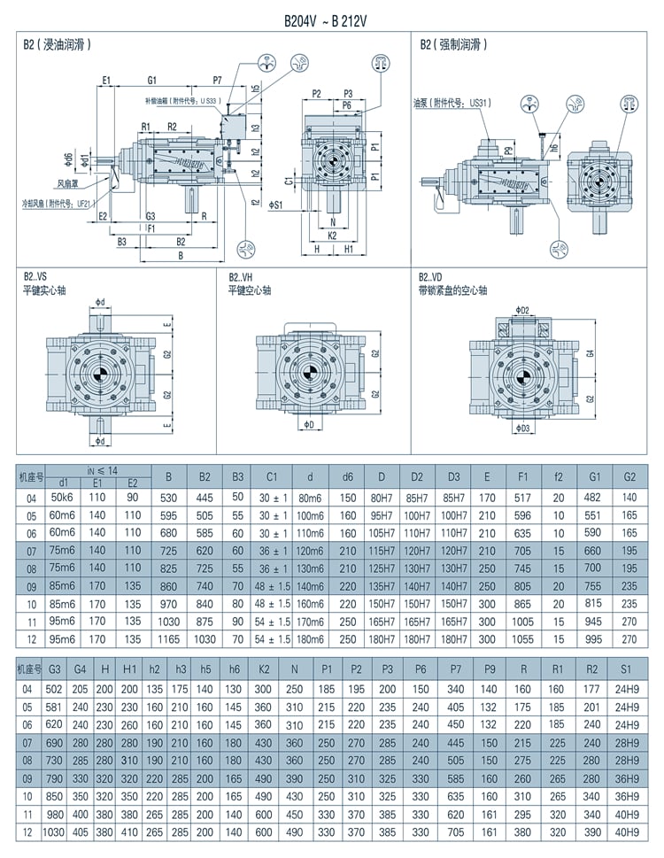
Model variety for washing equipment Gear Box Transmission:
Intently making use of the excellent reduction ratio.
Reduction ratio = servo motor speed / reducer output shaft pace
Torque calculation: Torque calculation is quite critical for the life of reducer, and shell out attention to whether the maximum torque price (TP) of acceleration exceeds the maximum load torque of the reducer.
The relevant energy is typically the relevant power of the servo types on the marketplace, the applicability of the reducer is extremely substantial, the working coefficient can be managed earlier mentioned 1.2, but the decision can also be primarily based on their own needs to determine. industrial helical gearbox.OEM Substantial Torque Helical Equipment Speed Reducer. H B right angle helical bevel equipment box 90 diploma transmission gearbox kind for sliding gate.
Technological innovation
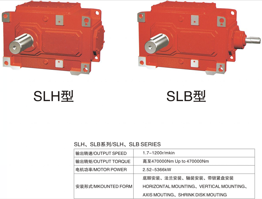
Chinese Speed Reducer/industrial helical gearbox is a mechanical transmission in numerous fields of the countrywide economy. The merchandise classes coated by the business incorporate all kinds of equipment reducer, planetary equipment reducer and worm gearbox, as nicely as numerous particular transmission devices such as pace growing unit, speed management Products, including different types of flexible transmission products, these kinds of as compound transmission. Goods and services in the subject of metallurgy, nonferrous metals, coal, creating resources, ships, water conservancy, electricity, design machinery and petrochemical industries.
In all fields of national economic climate and nationwide defense sector, gearbox products have a extensive variety of purposes. Foodstuff gentle business, electric powered machinery, construction machinery, metallurgy machinery, cement equipment, environmental safety machinery, digital appliances, road construction equipment, h2o conservancy equipment, chemical equipment, mining equipment, conveyor machinery, constructing materials machinery, rubber machinery, petroleum machinery and other industries have sturdy demand of Reducer goods. H B appropriate angle helical bevel gear box 90 degree transmission gearbox kind for sliding gate.
Packaging & Delivery

- one. Big Volecity- Minimizing Ratio:Ratio of solitary-phase pace-decreasing is 1/eleven-1/87 Ratio of double phase velocity-minimizing is 1/112-1/5133Ratio of 3-phase speed-minimizing is 1/2057-1/446571more-levels can be merged according to the requirement.
-
two. High driving performance:Due to adopting rolling engagement in falling-in element, the driving efficiency can get to earlier mentioned ninety%.
-
3. Small in size, mild fat: with compacted construction,small measurement and gentle fat. Because of to adopting the principle of earth driving so that the enter and output shaft in the very same axis which will built-in with the motor.H B proper angle helical bevel gear box ninety degree transmission gearbox kind for sliding gate
-
4. Long support existence: Has excellent resistance to abrasion because the main driving engaging elements are made of bearing steel and making use of rolling friction.
-
5. Stable working: for most driving method, we adopt multi-enamel slipping-in. Then the managing will be secure with reduced sounds.
-
6. Convenient dismounting:affordable structure and design and style.
-
seven. Strong overloading ability,anti-compact,ideal for frequently commence and double-aspect rotation.
Firm Details
Launched in 1995, HangZhou At any time-Electrical power Power machinery Co.,Ltd has 22 a long time of reducer manufacturing knowledge and trustworthiness. The firm has professional engineer crew, advanced technological innovation manufacturing and competent staff, with located in HangZhou of ZheJiang province which has solid industrial foundation and produced transportation.
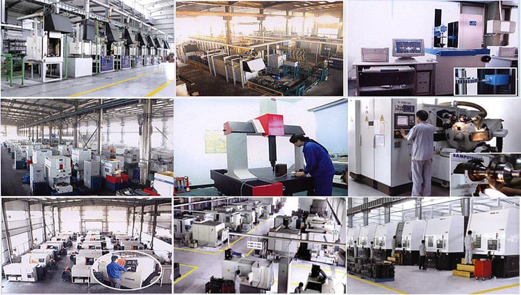
FAQ
1.Q:Are you the manufacturing unit or buying and selling organization?
A:We are the expert Manufacturing facility with 22 many years of encounter.
two.Q:Can you personalize according to our requirements?
A:Yes, we can design nonstandard products according to customer’s drawing and sample.
three.Q:How lengthy is the shipping and delivery date?
A:ten-twenty working days.
4.Q:The place is your manufacturing facility?
A:We are in HangZhou of ZheJiang Province, you can get below by substantial speed prepare or fly to Jinan.
Welcome to check out us!
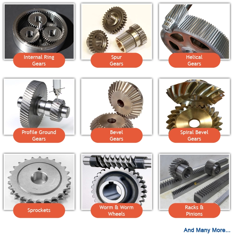


Screw made in China – replacement parts – in Ulaanbaatar Mongolia Air Compressor Parts Gear Wheel Stainless Steel Double Helical Gear Set 1614930800 0900 with ce certificate top quality low price
We – EPG Group the bigge EPT Chain and agricultural gearbox manufacturing facility in China with 5 distinct branches. For more information: Cellular/whatsapp/telegram/Kakao us at: 0086~13083988828 13858117778 0571 88828
Screw Air Compressor Elements Compressed Gear Wheels
Manufacturing information
Specs
Chain Wheel Sprocket:
one.European Standard and American Standard.
2.Processing: Forging hobbing,Quenching,CNC Machining.
Small Spur Gear:
Features
one. Strict quality inspection during every production step from producing to the ending packing process.
2. Exporting products with good quality and best price.
3.Excellent customers using report from both domestic marketing and abroad.
four. The using of advanced processing technology of milling teeth , tooth shape to make more accurate. And the whole process modulated heat, greatly improve the comprehensive mechanical properties. Tooth hardness above 40-60HRC, the wear resistance of the sprocket improve.
5. Variety of sprockets can be processed to meet your requirements,standard sprockets (DIN. ANSI. KANA)Non-standard sprockets (especially the OEM is most welcome).
6.The original designs is available(we can design the items base on your requirements).
seven. Our extensive knowledge and experience with sprocket drives allows us to work together with our customers to solve the problem and help improve the longevity and performance of your chain drive. We have the knowledge, resources and stock to solve those problems and annoying issues. The production of high precision and long life of the product is always our top priority.
our companies
24 hrs a day, 7 days a 7 days
1-cease buying
Cheap, fast and efficient
| Enterprise scope | ||
| Mechanical Seal : |
Temperature Sensor | Strain Sensor |
| Maintenance Kits | Solenoid Valve | Thermostatic Valve |
| Air ingestion | Wheel Gear |
Stress Maintaining Valve |
| Air Filter | Oil Separator | Oil Filter |
| Oil Amount Indicator | Circuit Board Learn Manage | Air consumption valve |
| Used air compressor | Air-end | Oil amount indicator |
why us
1.24 hrs a working day, 7 times a week
2.1-quit buying
3.Cheap, fast and successful
4.sufficient shares
5.12 a long time activities
6. Critically top quality manage
7.Superb technique
Appendix—element no. li EPT of our merchandise.
| NO | Design | Description | P/N |
| one | GA11-22 | Unloading valve package | 295715711 |
| 2 | Min strain valve kit | 2957100600 | |
| 3 | Drain valve kit | 2957171200 | |
| four | GA30-37-forty five | Drain valve package | 2957121900 |
| 5 | Min force valve kit | 2957121800 | |
| 6 | Examine valve kit | 2957121200 | |
| 7 | Oil quit valve package | 2957121700 | |
| 8 | Unloading valve package | 2957121100 | |
| nine | Thermostat valve package | 1619733300 | |
| 10 | GA55-75-90C | Oil examine valve kit | 2957107200 |
| eleven | Verify valve kit | 29571 0571 | |
| 12 | Min pressure valve package | 2957121800 | |
| thirteen | Unloading valve package | 2957144800 | |
| fourteen | Thermostat valve package | 2957107400 | |
| 15 | Drain valve kit | 2957184500 | |
| 16 | Drain valve package | 295715710 | |
| seventeen | Oil stop valve kit | 2901108400 | |
| eighteen | Unloading valve kit | 2957129900 | |
| 19 | GA90-250 | Te EPT valve package | 29060 0571 |
| twenty | Oil check out valve kit | 2906009400 | |
| 21 | Min stress valve kit | 2906009600 | |
| 22 | Regulating valve package | 290605710 | |
| 23 | Thermostat valve package | 1619756000 | |
| 24 | Unloading valve kit | 2906 0571 00 | |
| 25 | Connector kit | 290657100 | |
| 26 | Drain valve kit | 2957174900 | |
| 27 | GA22+ | Unloading valve kit | 2957116100(with blow off valve) |
| 28 | Unloading valve package | 2957116100(with no blow off valve) | |
| 29 | Examine valve package | 2957150301 | |
| Oil quit valve package | 2957121701 | ||
| thirty | Min pressure valve kit | 2901145300 | |
| 31 | Thermostat valve kit | 2901161600 | |
| 32 | GA37+ | Unloading valve package | 2901162200(with blow off valve) |
| 33 | Unloading valve kit | 2901162200(with no blow off valve) | |
| 34 | Examine valve package | 2957150301 | |
| 35 | Oil end valve kit | 2901108401 | |
| 36 | Min pressure valve kit | 2901145300 | |
| 37 | Thermostat valve package | 2901161600 | |
| 38 | GA75+ | Unloading valve kit | 2901146300(with blow off valve) |
| 39 | Unloading valve kit | 2901146300(with out blow off valve) | |
| 40 | Check out valve kit | 2957150301 | |
| forty one | Oil end valve package | 2901108401 | |
| 42 | Min pressure valve kit | 2901145300 | |
| forty three | Thermostat valve kit | 1622375980 |
No matter what you want, ju EPT ship me your part no. , favorable price tag will be quoted quickly. our aim is to “supply the be EPT goods and solutions to our buyers”
1.High Top quality With Favorable Cost
We make certain that the parts we provide are achieved your demands with higher top quality , but the costs are a lot decrease than the unique elements, because we specialised in this discipline for more than ten several years, can supply a complete range of air compressor elements with favorable costs.
2.Higher operate Effiency With Fa EPT Delivery
We have a specialist team with strong warehousing and distribution ability, so we’re in a position to be quicker than EPT suppliers in effectiveness.
The use of authentic gear manufacturer’s (OEM) element figures or trademarks , e.g. CASE® and John Deere® are for reference purposes only and for indicating merchandise use and compatibility. Our organization and the detailed substitute elements contained herein are not sponsored, approved, or made by the OEM.