Product Description
| Basic Info. of Our Customized CNC Machining Parts | |
| Quotation | According To Your Drawings or Samples. (Size, Material, Thickness, Processing Content And Required Technology, etc.) |
| Tolerance | +/-0.005 – 0.01mm (Customizable) |
| Surface Roughness | Ra0.2 – Ra3.2 (Customizable) |
| Materials Available | Aluminum, Copper, Brass, Stainless Steel, Titanium, Iron, Plastic, Acrylic, PE, PVC, ABS, POM, PTFE etc. |
| Surface Treatment | Polishing, Surface Chamfering, Hardening and Tempering, Nickel plating, Chrome plating, zinc plating, Laser engraving, Sandblasting, Passivating, Clear Anodized, Color Anodized, Sandblast Anodized, Chemical Film, Brushing, etc. |
| Processing | Hot/Cold forging, Heat treatment, CNC Turning, Milling, Drilling and Tapping, Surface Treatment, Laser Cutting, Stamping, Die Casting, Injection Molding, etc. |
| Testing Equipment | Coordinate Measuring Machine (CMM) / Vernier Caliper/ / Automatic Height Gauge /Hardness Tester /Surface Roughness Teste/Run-out Instrument/Optical Projector, Micrometer/ Salt spray testing machine |
| Drawing Formats | PRO/E, Auto CAD, CHINAMFG Works , UG, CAD / CAM / CAE, PDF |
| Our Advantages | 1.) 24 hours online service & quickly quote and delivery. 2.) 100% quality inspection (with Quality Inspection Report) before delivery. All our products are manufactured under ISO 9001:2015. 3.) A strong, professional and reliable technical team with 16+ years of manufacturing experience. 4.) We have stable supply chain partners, including raw material suppliers, bearing suppliers, forging plants, surface treatment plants, etc. 5.) We can provide customized assembly services for those customers who have assembly needs. |
| Available Material | |
| Stainless Steel | SS201,SS301, SS303, SS304, SS316, SS416, etc. |
| Steel | mild steel, Carbon steel, 4140, 4340, Q235, Q345B, 20#, 45#, etc. |
| Brass | HPb63, HPb62, HPb61, HPb59, H59, H62, H68, H80, etc. |
| Copper | C11000, C12000,C12000, C36000 etc. |
| Aluminum | A380, AL2571, AL6061, Al6063, AL6082, AL7075, AL5052, etc. |
| Iron | A36, 45#, 1213, 12L14, 1215 etc. |
| Plastic | ABS, PC, PE, POM, Delrin, Nylon, PP, PEI, Peek etc. |
| Others | Various types of Titanium alloy, Rubber, Bronze, etc. |
| Available Surface Treatment | |
| Stainless Steel | Polishing, Passivating, Sandblasting, Laser engraving, etc. |
| Steel | Zinc plating, Oxide black, Nickel plating, Chrome plating, Carburized, Powder Coated, etc. |
| Aluminum parts | Clear Anodized, Color Anodized, Sandblast Anodized, Chemical Film, Brushing, Polishing, etc. |
| Plastic | Plating gold(ABS), Painting, Brushing(Acylic), Laser engraving, etc. |
FAQ:
Q1: Are you a trading company or a factory?
A1: We are a factory
Q2: How long is your delivery time?
A2: Samples are generally 3-7 days; bulk orders are 10-25 days, depending on the quantity and parts requirements.
Q3: Do you provide samples? Is it free or extra?
A3: Yes, we can provide samples, and we will charge you based on sample processing. The sample fee can be refunded after placing an order in batches.
Q4: Do you provide design drawings service?
A4: We mainly customize according to the drawings or samples provided by customers. For customers who don’t know much about drawing, we also provide design and drawing services. You need to provide samples or sketches.
Q5: What about drawing confidentiality?
A5: The processed samples and drawings are strictly confidential and will not be disclosed to anyone else.
Q6: How do you guarantee the quality of your products?
A6: We have set up multiple inspection procedures and can provide quality inspection report before delivery. And we can also provide samples for you to test before mass production.
/* January 22, 2571 19:08:37 */!function(){function s(e,r){var a,o={};try{e&&e.split(“,”).forEach(function(e,t){e&&(a=e.match(/(.*?):(.*)$/))&&1
| Certification: | CE, RoHS, GS, ISO9001 |
|---|---|
| Standard: | DIN, ASTM, GOST, GB, JIS, ANSI, BS |
| Customized: | Customized |
| Material: | Metal |
| Application: | Metal Recycling Machine, Metal Cutting Machine, Metal Straightening Machinery, Metal Spinning Machinery, Metal Processing Machinery Parts, Metal forging Machinery, Metal Engraving Machinery, Metal Drawing Machinery, Metal Coating Machinery, Metal Casting Machinery |
| Tolerance: | +/-0.005 – 0.01mm |
| Samples: |
US$ 1/Piece
1 Piece(Min.Order) | |
|---|
| Customization: |
Available
| Customized Request |
|---|

What are the different types of spline profiles and their applications?
Spline profiles are used in various applications to transmit torque and motion between mating components. Here’s a detailed explanation of different spline profiles and their applications:
1. Involute Splines:
Involute splines have a trapezoidal tooth profile that allows for smooth engagement and disengagement. They are widely used in power transmission applications, such as automotive gearboxes, where high torque transmission is required. Involute splines provide excellent load distribution and can accommodate misalignment.
2. Straight Sided Splines:
Straight sided splines have straight-sided teeth that provide efficient torque transmission and high torsional stiffness. They are commonly used in applications where precise positioning is required, such as machine tools, robotics, and aerospace systems. Straight sided splines offer accurate motion control and are resistant to misalignment.
3. Serrations:
Serrations are a type of spline profile with multiple teeth in the form of parallel ridges and grooves. They are often used in applications that involve axial or linear motion, such as indexing mechanisms, clamping systems, or power tools. Serrations provide secure locking and positioning capabilities.
4. Helical Splines:
Helical splines have teeth that are helically shaped, similar to helical gears. They offer smooth and gradual tooth engagement, resulting in reduced noise and vibration. Helical splines are commonly used in applications that require high torque transmission and where quiet operation is critical, such as heavy machinery, industrial equipment, and automotive drivetrains.
5. Crowned Splines:
Crowned splines have a modified tooth profile with a slight curvature along the tooth length. This design helps distribute the load evenly across the tooth surfaces, reducing stress concentrations and improving load-carrying capacity. Crowned splines are used in applications where high load capacity and resistance to wear are essential, such as heavy-duty gearboxes, marine propulsion systems, or mining equipment.
6. Ball Splines:
Ball splines incorporate recirculating ball bearings within the spline nut and grooves on the shaft. This design enables linear motion with low friction and high precision. Ball splines are commonly used in applications that require smooth linear motion, such as CNC machines, robotics, or linear actuators.
7. Custom Splines:
In addition to the standard spline profiles mentioned above, custom spline profiles can be designed for specific applications based on unique requirements. Custom splines can be tailored to optimize torque transmission, load distribution, misalignment compensation, or other specific performance parameters.
The choice of spline profile depends on factors such as the magnitude of torque, required accuracy, misalignment tolerance, noise and vibration considerations, and environmental conditions. Engineers and designers carefully select the appropriate spline profile to ensure optimal performance and reliability in the intended application.

Can spline shafts be repaired or maintained when necessary?
Yes, spline shafts can be repaired and maintained when necessary to ensure their continued functionality and performance. Here are some ways spline shafts can be repaired and maintained:
1. Inspection and Assessment:
When an issue is suspected with a spline shaft, the first step is to conduct a thorough inspection. This involves examining the shaft for any signs of wear, damage, or misalignment. Special attention is given to the spline teeth, which may show signs of wear or deformation. Through inspection and assessment, the extent of the repair or maintenance required can be determined.
2. Spline Tooth Repair:
If the spline teeth are damaged or worn, they can be repaired or replaced. Repair methods may include re-machining the teeth to restore their original profile, filling and reshaping the worn areas using specialized welding techniques, or replacing the damaged section of the spline shaft. The specific repair method depends on the severity of the damage and the material of the spline shaft.
3. Lubrication and Cleaning:
Regular lubrication and cleaning are essential for maintaining spline shafts. Lubricants help reduce friction and wear between the mating surfaces, while cleaning removes contaminants that can affect the spline’s engagement. During maintenance, old lubricants are removed, and fresh lubricants are applied to ensure smooth operation and prevent premature failure.
4. Surface Treatment:
If the spline shaft undergoes wear or corrosion, surface treatment can be applied to restore its condition. This may involve applying coatings or treatments to enhance the hardness, wear resistance, or corrosion resistance of the spline shaft. Surface treatments can improve the longevity and performance of the spline shaft, reducing the need for frequent repairs.
5. Balancing and Alignment:
If a spline shaft is experiencing vibration or misalignment issues, it may require balancing or realignment. Balancing involves redistributing mass along the shaft to minimize vibrations, while alignment ensures proper mating and engagement with other components. Balancing and alignment procedures help optimize the performance and longevity of the spline shaft.
6. Replacement:
In cases where the spline shaft is severely damaged or worn beyond repair, replacement may be necessary. Replacement spline shafts can be sourced from manufacturers or specialized suppliers who can provide shafts that meet the required specifications and tolerances.
It’s important to note that the repair and maintenance of spline shafts should be carried out by qualified professionals with expertise in precision machining and mechanical systems. They have the knowledge and tools to properly assess, repair, or replace spline shafts, ensuring the integrity and functionality of the system in which they are used.
By implementing regular maintenance and timely repairs, spline shafts can be kept in optimal condition, extending their lifespan and maintaining their performance in various mechanical applications.

Can you explain the common applications of spline shafts in machinery?
Spline shafts have various common applications in machinery where torque transmission, relative movement, and load distribution are essential. Here’s a detailed explanation:
1. Gearboxes and Transmissions:
Spline shafts are commonly used in gearboxes and transmissions where they facilitate the transmission of torque from the input shaft to the output shaft. The splines on the shaft engage with corresponding splines on the gears, allowing for precise torque transfer and accommodating relative movement between the gears.
2. Power Take-Off (PTO) Units:
In agricultural and industrial machinery, spline shafts are employed in power take-off (PTO) units. PTO units allow the transfer of power from the engine to auxiliary equipment, such as pumps, generators, or farm implements. Spline shafts enable the torque transfer and accommodate the relative movement required for PTO operation.
3. Steering Systems:
Spline shafts play a crucial role in steering systems, especially in vehicles. They are used in steering columns to transmit torque from the steering wheel to the steering rack or gearbox. The splines on the shaft ensure precise torque transfer while allowing for the axial movement required for steering wheel adjustment.
4. Machine Tools:
Spline shafts find applications in machine tools such as milling machines, lathes, and grinding machines. They are used to transmit torque and enable the relative movement required for tool positioning, feed control, and spindle rotation. Spline shafts ensure accurate and controlled movement of the machine tool components.
5. Industrial Pumps and Compressors:
Spline shafts are utilized in various types of pumps and compressors, including centrifugal pumps, gear pumps, and reciprocating compressors. They transmit torque from the driver (such as an electric motor or an engine) to the impeller or rotor, enabling fluid or gas transfer. Spline shafts accommodate the axial or radial movement caused by thermal expansion or misalignment.
6. Printing and Packaging Machinery:
Spline shafts are integral components in printing and packaging machinery. They are used in processes such as web handling, where precise torque transmission and relative movement are required for tasks like tension control, registration, and material feeding. Spline shafts ensure accurate and synchronized movement of the printing and packaging elements.
7. Aerospace and Defense Systems:
In the aerospace and defense industries, spline shafts are utilized in various applications, including aircraft landing gear systems, missile guidance systems, and helicopter rotor systems. They enable torque transmission, accommodate relative movement, and ensure precise control in critical aerospace and defense mechanisms.
8. Construction and Earthmoving Equipment:
Spline shafts are employed in construction and earthmoving equipment, such as excavators, bulldozers, and loaders. They are used in hydraulic systems to transmit torque from the hydraulic motor to the driven components, such as the digger arm or the bucket. Spline shafts enable efficient power transfer and allow for the articulation and movement of the equipment.
These are just a few examples of the common applications of spline shafts in machinery. Their versatility, torque transmission capabilities, and ability to accommodate relative movement make them essential components in various industries where precise power transfer and flexibility are required.


editor by CX 2024-04-16
China Good quality Custom CNC Machining Turning Spline Bolt Nut Hollow Threaded Spindle Gear Steel Propeller Drive Shaft of Motorcycle Electric Motor Auto Generator Transmission
Product Description
| Basic Info. of Our Customized CNC Machining Parts | |
| Quotation | According To Your Drawings or Samples. (Size, Material, Thickness, Processing Content And Required Technology, etc.) |
| Tolerance | +/-0.005 – 0.01mm (Customizable) |
| Surface Roughness | Ra0.2 – Ra3.2 (Customizable) |
| Materials Available | Aluminum, Copper, Brass, Stainless Steel, Titanium, Iron, Plastic, Acrylic, PE, PVC, ABS, POM, PTFE etc. |
| Surface Treatment | Polishing, Surface Chamfering, Hardening and Tempering, Nickel plating, Chrome plating, zinc plating, Laser engraving, Sandblasting, Passivating, Clear Anodized, Color Anodized, Sandblast Anodized, Chemical Film, Brushing, etc. |
| Processing | Hot/Cold forging, Heat treatment, CNC Turning, Milling, Drilling and Tapping, Surface Treatment, Laser Cutting, Stamping, Die Casting, Injection Molding, etc. |
| Testing Equipment | Coordinate Measuring Machine (CMM) / Vernier Caliper/ / Automatic Height Gauge /Hardness Tester /Surface Roughness Teste/Run-out Instrument/Optical Projector, Micrometer/ Salt spray testing machine |
| Drawing Formats | PRO/E, Auto CAD, CHINAMFG Works , UG, CAD / CAM / CAE, PDF |
| Our Advantages | 1.) 24 hours online service & quickly quote and delivery. 2.) 100% quality inspection (with Quality Inspection Report) before delivery. All our products are manufactured under ISO 9001:2015. 3.) A strong, professional and reliable technical team with 16+ years of manufacturing experience. 4.) We have stable supply chain partners, including raw material suppliers, bearing suppliers, forging plants, surface treatment plants, etc. 5.) We can provide customized assembly services for those customers who have assembly needs. |
| Available Material | |
| Stainless Steel | SS201,SS301, SS303, SS304, SS316, SS416, etc. |
| Steel | mild steel, Carbon steel, 4140, 4340, Q235, Q345B, 20#, 45#, etc. |
| Brass | HPb63, HPb62, HPb61, HPb59, H59, H62, H68, H80, etc. |
| Copper | C11000, C12000,C12000, C36000 etc. |
| Aluminum | A380, AL2571, AL6061, Al6063, AL6082, AL7075, AL5052, etc. |
| Iron | A36, 45#, 1213, 12L14, 1215 etc. |
| Plastic | ABS, PC, PE, POM, Delrin, Nylon, PP, PEI, Peek etc. |
| Others | Various types of Titanium alloy, Rubber, Bronze, etc. |
| Available Surface Treatment | |
| Stainless Steel | Polishing, Passivating, Sandblasting, Laser engraving, etc. |
| Steel | Zinc plating, Oxide black, Nickel plating, Chrome plating, Carburized, Powder Coated, etc. |
| Aluminum parts | Clear Anodized, Color Anodized, Sandblast Anodized, Chemical Film, Brushing, Polishing, etc. |
| Plastic | Plating gold(ABS), Painting, Brushing(Acylic), Laser engraving, etc. |
FAQ:
Q1: Are you a trading company or a factory?
A1: We are a factory
Q2: How long is your delivery time?
A2: Samples are generally 3-7 days; bulk orders are 10-25 days, depending on the quantity and parts requirements.
Q3: Do you provide samples? Is it free or extra?
A3: Yes, we can provide samples, and we will charge you based on sample processing. The sample fee can be refunded after placing an order in batches.
Q4: Do you provide design drawings service?
A4: We mainly customize according to the drawings or samples provided by customers. For customers who don’t know much about drawing, we also provide design and drawing services. You need to provide samples or sketches.
Q5: What about drawing confidentiality?
A5: The processed samples and drawings are strictly confidential and will not be disclosed to anyone else.
Q6: How do you guarantee the quality of your products?
A6: We have set up multiple inspection procedures and can provide quality inspection report before delivery. And we can also provide samples for you to test before mass production.
/* January 22, 2571 19:08:37 */!function(){function s(e,r){var a,o={};try{e&&e.split(“,”).forEach(function(e,t){e&&(a=e.match(/(.*?):(.*)$/))&&1
| Certification: | CE, RoHS, GS, ISO9001 |
|---|---|
| Standard: | DIN, ASTM, GOST, GB, JIS, ANSI, BS |
| Customized: | Customized |
| Material: | Metal |
| Application: | Metal Recycling Machine, Metal Cutting Machine, Metal Straightening Machinery, Metal Spinning Machinery, Metal Processing Machinery Parts, Metal forging Machinery, Metal Engraving Machinery, Metal Drawing Machinery, Metal Coating Machinery, Metal Casting Machinery |
| Tolerance: | +/-0.005 – 0.01mm |
| Samples: |
US$ 1/Piece
1 Piece(Min.Order) | |
|---|
| Customization: |
Available
| Customized Request |
|---|

Can spline shafts be used in both mobile and stationary machinery?
Yes, spline shafts can be used in both mobile and stationary machinery. Here’s a detailed explanation:
1. Mobile Machinery:
Spline shafts find extensive use in various types of mobile machinery. For example:
- In Automotive Applications: Spline shafts are commonly used in automotive drivetrains, where they transmit torque from the engine to the wheels. They are found in components such as the transmission, differential, and axle shafts.
- In Construction and Earthmoving Equipment: Spline shafts are utilized in construction machinery, such as excavators, loaders, and bulldozers. They are employed in the powertrain systems to transfer torque and drive the hydraulic pumps or propel the machine.
- In Agricultural Equipment: Spline shafts are used in agricultural machinery like tractors, combines, and harvesters. They help transfer power from the engine to various driven components, such as the wheels, PTO (power take-off), or hydraulic systems.
- In Off-Road Vehicles: Spline shafts are present in off-road vehicles, including ATVs (all-terrain vehicles) and military vehicles. They enable power transmission to the wheels or drivetrain components, ensuring mobility and performance in challenging terrains.
2. Stationary Machinery:
Spline shafts are also widely employed in stationary machinery across various industries. Some examples include:
- In Machine Tools: Spline shafts are used in machine tools, such as lathes, milling machines, and grinding machines. They provide torque transmission in the spindle or lead screw mechanisms, enabling precision motion control and material removal operations.
- In Industrial Gearboxes: Spline shafts play a crucial role in industrial gearboxes used in manufacturing and processing plants. They transmit torque between input and output shafts, enabling speed reduction or increase as required by the application.
- In Power Generation: Spline shafts are utilized in power generation equipment, including turbines and generators. They help transmit torque between the rotating rotor and the stationary components, facilitating energy conversion.
- In Pump and Compressor Systems: Spline shafts are present in pumps and compressors used in various industries. They transmit torque from the motor or prime mover to the impeller or compressor elements, enabling fluid or gas transfer.
The versatility of spline shafts makes them suitable for a wide range of applications, both mobile and stationary. Their ability to efficiently transmit torque, accommodate misalignment, distribute loads, and provide reliable connections makes them a preferred choice in diverse machinery across industries.

What materials are commonly used in the construction of spline shafts?
Various materials are commonly used in the construction of spline shafts, depending on the specific application requirements. Here’s a list of commonly used materials:
1. Steel:
Steel is one of the most widely used materials for spline shafts. Different grades of steel, such as carbon steel, alloy steel, or stainless steel, can be employed based on factors like strength, hardness, and corrosion resistance. Steel offers excellent mechanical properties, including high strength, durability, and wear resistance, making it suitable for a broad range of applications.
2. Alloy Steel:
Alloy steel is a type of steel that contains additional alloying elements, such as chromium, molybdenum, or nickel. These alloying elements enhance the mechanical properties of the steel, providing improved strength, toughness, and wear resistance. Alloy steel spline shafts are commonly used in applications that require high torque capacity, durability, and resistance to fatigue.
3. Stainless Steel:
Stainless steel is known for its corrosion resistance properties, making it suitable for applications where the spline shaft is exposed to moisture or corrosive environments. Stainless steel spline shafts are commonly used in industries such as food processing, chemical processing, marine, and medical equipment.
4. Aluminum:
Aluminum is a lightweight material with good strength-to-weight ratio. It is often used in applications where weight reduction is a priority, such as automotive and aerospace industries. Aluminum spline shafts can provide advantages such as decreased rotating mass and improved fuel efficiency.
5. Titanium:
Titanium is a strong and lightweight material with excellent corrosion resistance. It is commonly used in high-performance applications where weight reduction, strength, and corrosion resistance are critical factors. Titanium spline shafts find applications in aerospace, motorsports, and high-end industrial equipment.
6. Brass:
Brass is an alloy of copper and zinc, offering good machinability and corrosion resistance. It is often used in applications that require electrical conductivity or a non-magnetic property. Brass spline shafts can be found in industries such as electronics, telecommunications, and instrumentation.
7. Plastics and Composite Materials:
In certain applications where weight reduction, corrosion resistance, or noise reduction is important, plastics or composite materials can be used for spline shafts. Materials such as nylon, acetal, or fiber-reinforced composites can provide specific advantages in terms of weight, low friction, and resistance to chemicals.
It’s important to note that material selection for spline shafts depends on factors such as load requirements, environmental conditions, operating temperatures, and cost considerations. Engineers and designers evaluate these factors to determine the most suitable material for a given application.

What are the advantages of using spline shafts in mechanical systems?
Using spline shafts in mechanical systems offers several advantages. Here’s a detailed explanation:
1. Torque Transmission:
Spline shafts provide efficient torque transmission between the driving and driven components. The interlocking splines ensure a secure and reliable transfer of rotational force, enabling the transmission of power and motion in mechanical systems.
2. Relative Movement Accommodation:
Spline shafts can accommodate relative movement between the driving and driven components. They allow axial, radial, and angular displacements, compensating for misalignments, thermal expansion, and vibrations. This flexibility helps to maintain proper engagement and minimize stress concentrations.
3. Load Distribution:
The splines on the shaft distribute the transmitted load across the entire engagement surface. This helps to reduce localized stresses and prevents premature wear or failure of the components. The load distribution capability of spline shafts contributes to the overall durability and longevity of the mechanical system.
4. Precise Positioning and Control:
Spline shafts enable precise positioning and control of mechanical components. The splines provide accurate rotational alignment, allowing for precise angular positioning and indexing. This is crucial in applications where precise control and synchronization of movements are required.
5. Interchangeability and Standardization:
Spline shafts are available in standardized designs and dimensions. This enables interchangeability between components and facilitates easier maintenance and replacement. Standardization also simplifies the design and manufacturing processes, reducing costs and lead times.
6. High Power Transmission Capacity:
Spline shafts are designed to withstand high torque loads. The interlocking splines provide a large contact area, distributing the transmitted torque across multiple teeth. This allows spline shafts to handle higher power transmission requirements, making them suitable for heavy-duty applications.
7. Versatility:
Spline shafts can be designed and manufactured to suit various application requirements. They can be customized in terms of size, shape, number of splines, and spline profile to match the specific needs of a mechanical system. This versatility makes spline shafts adaptable to a wide range of industries and applications.
8. Reduced Slippage and Backlash:
When properly designed and manufactured, spline shafts exhibit minimal slippage and backlash. The tight fit between the splines prevents significant axial or radial movement during torque transmission, resulting in improved efficiency and precision in mechanical systems.
In summary, the advantages of using spline shafts in mechanical systems include efficient torque transmission, accommodation of relative movement, load distribution, precise positioning and control, interchangeability, high power transmission capacity, versatility, and reduced slippage and backlash. These advantages make spline shafts a reliable and effective choice in various applications where power transfer, flexibility, and precise motion control are essential.
editor by CX 2024-04-12
China supplier Custom CNC Machining Turning Spline Bolt Nut Hollow Threaded Spindle Gear Steel Propeller Drive Shaft of Motorcycle Electric Motor Auto Generator Transmission
Product Description
| No. | Item | Specifications |
| 1 | Materials | Carbon steel: 10#, 18#, 1018, 22#, 1571, 40Cr, 45#, 1045, 50#, 55#, 60#, 65Mn, 70#, 72B, 80#, 82B Alloy Structure Steel: B7, 20CrMo, 42Crmo, SCM415, SCM440, 4140 High-carbon chromium bearing steel: GCr15, 52100, SUJ2 Free-cutting steel: 12L14, 12L15 Stainless steel: 1Cr13, 2Cr13, 3Cr13, 4Cr13, 1Cr17, SUS410, SUS420, SUS430, SUS416, SUS440C, 17-4, 17-4PH, 130M, 200, 201, 202, 205, 303, 303Cu, 304, 316, 316L Aluminum grade: 6061, 6063 Brass: Hpb58-2.5 (C38000), Hpb59-1 (C37710), Hpb61-1 (C37100), Hpb62-0.8 (C35000), Hpb63-0.1 (C34900), Hpb63-3 (C34500), H60, H62, H63, H65 |
| 2 | Diameter | Ø0.3-Ø25 |
| 3 | Diameter tolerance | 0.002mm |
| 4 | Roundness | 0.0005mm |
| 5 | Roughness | Ra0.05 |
| 6 | Straightness | 0.005mm |
| 7 | Hardness: | HRC/HV |
| 8 | Length | 2mm-1000mm |
| 9 | Heat treatment | 1. Oil Quenching 2. High frequency quenching 3. Carburization 4. Vacuum Heat treatment 5. Mesh belt CHINAMFG heat treatment |
| 10 | Surface treatment | 1. Plating nickel 2. Plating zinc 3. Plating passivation 4. Plating phosphating 5. Black coating 6. Anodized treatment |
| 11 | Packing | Plastic bags inside and standard cartons outside. Shipment by pallets or according to customer’s packing specifications. |
ZheJiang Sanrui Precision Co., Ltd. supplies cast iron and steel components in North China.
We have been in the business of these products since 1997 and export our products to the USA and EU.
We have following methods to produce:
1. Automatic line, model box at 900X900
2.Shell moulding
3.Lost wax casting
4.Machining from Tube, bar
5.Steel sheet cutting and machining
We have special advantage in the following products:
1. Components for agricultural equipment, construction and mining equipment, typical products include: wheel hubs, wheels, counter weight , 3 points for lifting system, etc.
2. Pump body, motor housing and valve body castings.
3. Concrete hose fittings
4. Pulleys, pulleys for glazing line.
Weight of castings we could supply: up to 5MT.
Dimension of castings: up to 2.5 Meter.
Material of castings: gray iron, ductile iron, carbon and alloy steel, investment stainless steel castings, etc .Our machine shop are equipped with both engine lathe for rough machining and CNC, MCs for finishing to meet the tolerance requirement and at the same time to maintain the lowest cost.
Physical Test: Hardness, Tensile strength, yield strength, elongation.
Chemical Test: C,Si,Mn,S,P and so on.
Surface treatment: Powder coating, Galvanization, Mirror polishing etc
We have experienced technicians, advanced equipment, modern and efficient management methods, reliable quality, and a policy of regarding the customer as the heart of service will ensure the continuous and steady development of our company. You can count on our expertise, including a staff foundry engineer, to assist in providing the best solution to lower the cost of your final products.
We will, as always, work together with our customers to seek opportunities for developing new market and products, to satisfy our customer and the society.
/* March 10, 2571 17:59:20 */!function(){function s(e,r){var a,o={};try{e&&e.split(“,”).forEach(function(e,t){e&&(a=e.match(/(.*?):(.*)$/))&&1
| After-sales Service: | Yes |
|---|---|
| Warranty: | Yes |
| Model No.: | OEM |
| Axis Shape: | Straight Shaft |
| Appearance Shape: | Round |
| Surface Finish: | Sandblasted/Anodized/Plated/Customized |
| Customization: |
Available
| Customized Request |
|---|
What are the different types of spline profiles and their applications?
Spline profiles are used in various applications to transmit torque and motion between mating components. Here’s a detailed explanation of different spline profiles and their applications:
1. Involute Splines:
Involute splines have a trapezoidal tooth profile that allows for smooth engagement and disengagement. They are widely used in power transmission applications, such as automotive gearboxes, where high torque transmission is required. Involute splines provide excellent load distribution and can accommodate misalignment.
2. Straight Sided Splines:
Straight sided splines have straight-sided teeth that provide efficient torque transmission and high torsional stiffness. They are commonly used in applications where precise positioning is required, such as machine tools, robotics, and aerospace systems. Straight sided splines offer accurate motion control and are resistant to misalignment.
3. Serrations:
Serrations are a type of spline profile with multiple teeth in the form of parallel ridges and grooves. They are often used in applications that involve axial or linear motion, such as indexing mechanisms, clamping systems, or power tools. Serrations provide secure locking and positioning capabilities.
4. Helical Splines:
Helical splines have teeth that are helically shaped, similar to helical gears. They offer smooth and gradual tooth engagement, resulting in reduced noise and vibration. Helical splines are commonly used in applications that require high torque transmission and where quiet operation is critical, such as heavy machinery, industrial equipment, and automotive drivetrains.
5. Crowned Splines:
Crowned splines have a modified tooth profile with a slight curvature along the tooth length. This design helps distribute the load evenly across the tooth surfaces, reducing stress concentrations and improving load-carrying capacity. Crowned splines are used in applications where high load capacity and resistance to wear are essential, such as heavy-duty gearboxes, marine propulsion systems, or mining equipment.
6. Ball Splines:
Ball splines incorporate recirculating ball bearings within the spline nut and grooves on the shaft. This design enables linear motion with low friction and high precision. Ball splines are commonly used in applications that require smooth linear motion, such as CNC machines, robotics, or linear actuators.
7. Custom Splines:
In addition to the standard spline profiles mentioned above, custom spline profiles can be designed for specific applications based on unique requirements. Custom splines can be tailored to optimize torque transmission, load distribution, misalignment compensation, or other specific performance parameters.
The choice of spline profile depends on factors such as the magnitude of torque, required accuracy, misalignment tolerance, noise and vibration considerations, and environmental conditions. Engineers and designers carefully select the appropriate spline profile to ensure optimal performance and reliability in the intended application.

Can spline shafts be applied in aerospace and aviation equipment?
Yes, spline shafts are commonly applied in aerospace and aviation equipment due to their ability to transmit torque and provide precise rotational motion. Here’s how spline shafts are used in the aerospace and aviation industry:
1. Aircraft Engines:
Spline shafts are utilized in aircraft engines for various purposes. They can be found in the engine’s accessory gearbox, where they transmit torque from the engine to drive auxiliary components such as fuel pumps, hydraulic pumps, generators, and engine starters. Spline shafts are also present in the engine’s variable geometry systems, which control the position of components like variable stator vanes or variable inlet guide vanes.
2. Flight Control Systems:
Spline shafts play a vital role in aircraft flight control systems. They are employed in the actuators and control mechanisms that operate the flaps, ailerons, elevators, rudders, and other control surfaces. Spline shafts enable precise and efficient transfer of control inputs from the cockpit to the respective control surfaces, contributing to the maneuverability and stability of the aircraft.
3. Landing Gear:
Spline shafts are used in the landing gear systems of aircraft. They can be found in components such as the landing gear actuator, which extends and retracts the landing gear, and the steering mechanism that controls the nose wheel. Spline shafts in landing gear systems need to withstand high loads, provide reliable operation, and ensure precise movement for safe and smooth landings and takeoffs.
4. Helicopter Rotors:
Helicopters rely on spline shafts in the main rotor assembly. The main rotor shaft, which transfers power from the helicopter’s engine to the rotor blades, often incorporates splines to ensure a secure connection and efficient torque transmission. Spline shafts are critical for maintaining stable and precise rotation of the rotor blades, allowing for controlled lift and maneuverability.
5. Auxiliary Systems:
Spline shafts are also applied in various auxiliary systems in aerospace and aviation equipment. These include systems such as power transmission for onboard generators, environmental control systems, fuel control systems, and hydraulic systems. Spline shafts in these applications contribute to the reliable operation and efficient functioning of the auxiliary equipment.
In aerospace and aviation applications, spline shafts are designed to meet stringent requirements for strength, durability, precision, and weight reduction. They are often made from high-strength materials such as titanium or alloy steel to withstand the demanding operating conditions and weight constraints of aircraft. Additionally, advanced manufacturing techniques are employed to ensure the dimensional accuracy and quality of spline shafts for critical aerospace applications.
The use of spline shafts in aerospace and aviation equipment enables precise control, efficient power transmission, and reliable operation, contributing to the safety, performance, and functionality of aircraft and related systems.
In which industries are spline shafts typically used?
Spline shafts find applications in a wide range of industries where torque transmission, relative movement, and load distribution are critical. Here’s a detailed explanation:
1. Automotive Industry:
The automotive industry extensively uses spline shafts in various components and systems. They are found in transmissions, drivelines, steering systems, differentials, and axle assemblies. Spline shafts enable the transmission of torque, accommodate relative movement, and ensure efficient power transfer in vehicles.
2. Aerospace and Defense Industry:
Spline shafts are essential in the aerospace and defense industry. They are used in aircraft landing gear systems, actuation mechanisms, missile guidance systems, engine components, and rotor assemblies. The aerospace and defense sector relies on spline shafts for precise torque transfer, relative movement accommodation, and critical control mechanisms.
3. Industrial Machinery and Equipment:
Spline shafts are widely employed in industrial machinery and equipment. They are used in gearboxes, machine tools, pumps, compressors, conveyors, printing machinery, and packaging equipment. Spline shafts enable torque transmission, accommodate misalignments and vibrations, and ensure accurate movement and synchronization of machine components.
4. Agriculture and Farming:
The agriculture and farming industry extensively uses spline shafts in equipment such as tractors, harvesters, and agricultural implements. Spline shafts are found in power take-off (PTO) units, transmission systems, hydraulic mechanisms, and steering systems. They enable torque transfer, accommodate relative movement, and provide flexibility in agricultural machinery.
5. Construction and Mining:
In the construction and mining industries, spline shafts are used in equipment such as excavators, loaders, bulldozers, and drilling rigs. They are found in hydraulic systems, power transmission systems, and articulated mechanisms. Spline shafts facilitate torque transmission, accommodate misalignments, and enable efficient power transfer in heavy-duty machinery.
6. Marine and Offshore:
Spline shafts have applications in the marine and offshore industry. They are used in propulsion systems, thrusters, rudders, winches, and marine pumps. Spline shafts enable torque transmission in marine vessels and offshore equipment, accommodating axial and radial movement, and ensuring reliable power transfer.
7. Energy and Power Generation:
Spline shafts are utilized in the energy and power generation sector. They are found in turbines, generators, compressors, and other rotating equipment. Spline shafts enable torque transmission and accommodate relative movement in power generation systems, ensuring efficient and reliable operation.
8. Rail and Transportation:
Spline shafts are employed in the rail and transportation industry. They are found in locomotives, railcar systems, and suspension mechanisms. Spline shafts enable torque transfer, accommodate movement and vibrations, and ensure precise control in rail and transportation applications.
These are just a few examples of the industries where spline shafts are typically used. Their versatility, torque transmission capabilities, and ability to accommodate relative movement make them vital components in various sectors that rely on efficient power transfer, flexibility, and precise control.
editor by CX 2024-02-01
China Professional Custom CNC Machining Turning Spline Bolt Nut Hollow Threaded Spindle Gear Steel Propeller Drive Shaft of Motorcycle Electric Motor Auto Generator Transmission
Product Description
| Basic Info. of Our Customized CNC Machining Parts | |
| Quotation | According To Your Drawings or Samples. (Size, Material, Thickness, Processing Content And Required Technology, etc.) |
| Tolerance | +/-0.005 – 0.01mm (Customizable) |
| Surface Roughness | Ra0.2 – Ra3.2 (Customizable) |
| Materials Available | Aluminum, Copper, Brass, Stainless Steel, Titanium, Iron, Plastic, Acrylic, PE, PVC, ABS, POM, PTFE etc. |
| Surface Treatment | Polishing, Surface Chamfering, Hardening and Tempering, Nickel plating, Chrome plating, zinc plating, Laser engraving, Sandblasting, Passivating, Clear Anodized, Color Anodized, Sandblast Anodized, Chemical Film, Brushing, etc. |
| Processing | Hot/Cold forging, Heat treatment, CNC Turning, Milling, Drilling and Tapping, Surface Treatment, Laser Cutting, Stamping, Die Casting, Injection Molding, etc. |
| Testing Equipment | Coordinate Measuring Machine (CMM) / Vernier Caliper/ / Automatic Height Gauge /Hardness Tester /Surface Roughness Teste/Run-out Instrument/Optical Projector, Micrometer/ Salt spray testing machine |
| Drawing Formats | PRO/E, Auto CAD, CHINAMFG Works , UG, CAD / CAM / CAE, PDF |
| Our Advantages | 1.) 24 hours online service & quickly quote and delivery. 2.) 100% quality inspection (with Quality Inspection Report) before delivery. All our products are manufactured under ISO 9001:2015. 3.) A strong, professional and reliable technical team with 16+ years of manufacturing experience. 4.) We have stable supply chain partners, including raw material suppliers, bearing suppliers, forging plants, surface treatment plants, etc. 5.) We can provide customized assembly services for those customers who have assembly needs. |
| Available Material | |
| Stainless Steel | SS201,SS301, SS303, SS304, SS316, SS416, etc. |
| Steel | mild steel, Carbon steel, 4140, 4340, Q235, Q345B, 20#, 45#, etc. |
| Brass | HPb63, HPb62, HPb61, HPb59, H59, H62, H68, H80, etc. |
| Copper | C11000, C12000,C12000, C36000 etc. |
| Aluminum | A380, AL2571, AL6061, Al6063, AL6082, AL7075, AL5052, etc. |
| Iron | A36, 45#, 1213, 12L14, 1215 etc. |
| Plastic | ABS, PC, PE, POM, Delrin, Nylon, PP, PEI, Peek etc. |
| Others | Various types of Titanium alloy, Rubber, Bronze, etc. |
| Available Surface Treatment | |
| Stainless Steel | Polishing, Passivating, Sandblasting, Laser engraving, etc. |
| Steel | Zinc plating, Oxide black, Nickel plating, Chrome plating, Carburized, Powder Coated, etc. |
| Aluminum parts | Clear Anodized, Color Anodized, Sandblast Anodized, Chemical Film, Brushing, Polishing, etc. |
| Plastic | Plating gold(ABS), Painting, Brushing(Acylic), Laser engraving, etc. |
FAQ:
Q1: Are you a trading company or a factory?
A1: We are a factory
Q2: How long is your delivery time?
A2: Samples are generally 3-7 days; bulk orders are 10-25 days, depending on the quantity and parts requirements.
Q3: Do you provide samples? Is it free or extra?
A3: Yes, we can provide samples, and we will charge you based on sample processing. The sample fee can be refunded after placing an order in batches.
Q4: Do you provide design drawings service?
A4: We mainly customize according to the drawings or samples provided by customers. For customers who don’t know much about drawing, we also provide design and drawing services. You need to provide samples or sketches.
Q5: What about drawing confidentiality?
A5: The processed samples and drawings are strictly confidential and will not be disclosed to anyone else.
Q6: How do you guarantee the quality of your products?
A6: We have set up multiple inspection procedures and can provide quality inspection report before delivery. And we can also provide samples for you to test before mass production.
/* March 10, 2571 17:59:20 */!function(){function s(e,r){var a,o={};try{e&&e.split(“,”).forEach(function(e,t){e&&(a=e.match(/(.*?):(.*)$/))&&1
| Certification: | CE, RoHS, GS, ISO9001 |
|---|---|
| Standard: | DIN, ASTM, GOST, GB, JIS, ANSI, BS |
| Customized: | Customized |
| Material: | Metal |
| Application: | Metal Recycling Machine, Metal Cutting Machine, Metal Straightening Machinery, Metal Spinning Machinery, Metal Processing Machinery Parts, Metal forging Machinery, Metal Engraving Machinery, Metal Drawing Machinery, Metal Coating Machinery, Metal Casting Machinery |
| Tolerance: | +/-0.005 – 0.01mm |
| Samples: |
US$ 1/Piece
1 Piece(Min.Order) | |
|---|
| Customization: |
Available
| Customized Request |
|---|
Can spline shafts be used in both mobile and stationary machinery?
Yes, spline shafts can be used in both mobile and stationary machinery. Here’s a detailed explanation:
1. Mobile Machinery:
Spline shafts find extensive use in various types of mobile machinery. For example:
- In Automotive Applications: Spline shafts are commonly used in automotive drivetrains, where they transmit torque from the engine to the wheels. They are found in components such as the transmission, differential, and axle shafts.
- In Construction and Earthmoving Equipment: Spline shafts are utilized in construction machinery, such as excavators, loaders, and bulldozers. They are employed in the powertrain systems to transfer torque and drive the hydraulic pumps or propel the machine.
- In Agricultural Equipment: Spline shafts are used in agricultural machinery like tractors, combines, and harvesters. They help transfer power from the engine to various driven components, such as the wheels, PTO (power take-off), or hydraulic systems.
- In Off-Road Vehicles: Spline shafts are present in off-road vehicles, including ATVs (all-terrain vehicles) and military vehicles. They enable power transmission to the wheels or drivetrain components, ensuring mobility and performance in challenging terrains.
2. Stationary Machinery:
Spline shafts are also widely employed in stationary machinery across various industries. Some examples include:
- In Machine Tools: Spline shafts are used in machine tools, such as lathes, milling machines, and grinding machines. They provide torque transmission in the spindle or lead screw mechanisms, enabling precision motion control and material removal operations.
- In Industrial Gearboxes: Spline shafts play a crucial role in industrial gearboxes used in manufacturing and processing plants. They transmit torque between input and output shafts, enabling speed reduction or increase as required by the application.
- In Power Generation: Spline shafts are utilized in power generation equipment, including turbines and generators. They help transmit torque between the rotating rotor and the stationary components, facilitating energy conversion.
- In Pump and Compressor Systems: Spline shafts are present in pumps and compressors used in various industries. They transmit torque from the motor or prime mover to the impeller or compressor elements, enabling fluid or gas transfer.
The versatility of spline shafts makes them suitable for a wide range of applications, both mobile and stationary. Their ability to efficiently transmit torque, accommodate misalignment, distribute loads, and provide reliable connections makes them a preferred choice in diverse machinery across industries.
What materials are commonly used in the construction of spline shafts?
Various materials are commonly used in the construction of spline shafts, depending on the specific application requirements. Here’s a list of commonly used materials:
1. Steel:
Steel is one of the most widely used materials for spline shafts. Different grades of steel, such as carbon steel, alloy steel, or stainless steel, can be employed based on factors like strength, hardness, and corrosion resistance. Steel offers excellent mechanical properties, including high strength, durability, and wear resistance, making it suitable for a broad range of applications.
2. Alloy Steel:
Alloy steel is a type of steel that contains additional alloying elements, such as chromium, molybdenum, or nickel. These alloying elements enhance the mechanical properties of the steel, providing improved strength, toughness, and wear resistance. Alloy steel spline shafts are commonly used in applications that require high torque capacity, durability, and resistance to fatigue.
3. Stainless Steel:
Stainless steel is known for its corrosion resistance properties, making it suitable for applications where the spline shaft is exposed to moisture or corrosive environments. Stainless steel spline shafts are commonly used in industries such as food processing, chemical processing, marine, and medical equipment.
4. Aluminum:
Aluminum is a lightweight material with good strength-to-weight ratio. It is often used in applications where weight reduction is a priority, such as automotive and aerospace industries. Aluminum spline shafts can provide advantages such as decreased rotating mass and improved fuel efficiency.
5. Titanium:
Titanium is a strong and lightweight material with excellent corrosion resistance. It is commonly used in high-performance applications where weight reduction, strength, and corrosion resistance are critical factors. Titanium spline shafts find applications in aerospace, motorsports, and high-end industrial equipment.
6. Brass:
Brass is an alloy of copper and zinc, offering good machinability and corrosion resistance. It is often used in applications that require electrical conductivity or a non-magnetic property. Brass spline shafts can be found in industries such as electronics, telecommunications, and instrumentation.
7. Plastics and Composite Materials:
In certain applications where weight reduction, corrosion resistance, or noise reduction is important, plastics or composite materials can be used for spline shafts. Materials such as nylon, acetal, or fiber-reinforced composites can provide specific advantages in terms of weight, low friction, and resistance to chemicals.
It’s important to note that material selection for spline shafts depends on factors such as load requirements, environmental conditions, operating temperatures, and cost considerations. Engineers and designers evaluate these factors to determine the most suitable material for a given application.
How does a spline shaft differ from other types of shafts?
A spline shaft differs from other types of shafts in several ways. Here’s a detailed explanation:
1. Spline Structure:
A spline shaft features a series of ridges or teeth (splines) that are machined onto its surface. These splines create a precise and controlled interface with mating components, allowing for torque transmission and relative movement. In contrast, other types of shafts, such as plain shafts or keyed shafts, do not have the splines and rely on different mechanisms for torque transmission.
2. Torque Transmission and Relative Movement:
Unlike plain shafts or keyed shafts, which transmit torque through a frictional or mechanical connection, spline shafts allow for both torque transmission and relative movement between the shaft and mating components. The splines on the shaft engage with corresponding splines on the mating component, creating an interlock that transfers rotational force while accommodating axial or radial displacement. This feature provides flexibility and is particularly useful in applications where misalignment or relative movement needs to be accommodated.
3. Load Distribution:
One of the advantages of spline shafts is their ability to distribute loads over a larger surface area. The multiple contact points created by the splines help distribute the applied load evenly along the shaft’s length. This load distribution minimizes stress concentrations and reduces the risk of premature wear or failure. In contrast, other types of shafts may rely on a single keyway or frictional contact, which can result in higher stress concentrations and limited load distribution.
4. Design Flexibility:
Spline shafts offer greater design flexibility compared to other types of shafts. The number, size, and shape of the splines can be customized to meet specific design requirements. This allows for optimization of torque transmission, load-bearing capacity, and relative movement characteristics based on the application’s needs. Other types of shafts may have more standardized designs and limited customization options.
5. Application Variability:
Spline shafts find widespread use in various industries and applications where torque transmission, relative movement, and load distribution are crucial. They are commonly employed in gearboxes, power transmission systems, steering mechanisms, and other rotational systems. Other types of shafts, such as plain shafts or keyed shafts, may be more suitable for applications that require simpler torque transmission without the need for relative movement.
6. Installation and Maintenance:
When compared to other types of shafts, spline shafts may require more precise machining and alignment during installation. The mating components must be accurately matched to ensure proper engagement and torque transfer. Additionally, spline shafts may require periodic inspection and maintenance to ensure the integrity of the splines and optimal performance.
In summary, spline shafts differ from other types of shafts due to their spline structure, ability to accommodate relative movement, load distribution capability, design flexibility, application variability, and specific installation and maintenance requirements. These characteristics make spline shafts well-suited for applications that demand precise torque transmission, flexibility, and load distribution.
editor by CX 2023-12-19
China high quality Custom Forging Steel Shaft Bevel Gear Spline Shaft with CNC Machining drive shaft electric motor
Product Description
| COMPANY PROFILE | |||||
| HangZhou HangZhoun Steel Co., Ltd is honored import and export rights by government. We are the professional manufacturer and exporter of special steel and steel solution provider. We worked in steel industry more than 15years, always to provide high quality, competitive price and good solution for customers. We owned good honors in domestic market and abroad market. Our products widely exported to EU,Asia, Middle east, Lati- america, Japan, Korea, Australia, and so on. |
|||||
| Our main products. Raw material in steel round bar, steel flat, steel plate, steel tube in carbon steel, alloy steel, tool steel, mould steel , bearing steel, stainless steel, super alloy, special alloy. And roller, shafts, cylinder, steel plank, steel rings, by casting, rolling, forged. Forgings according to drawings. We also provide steel machinery processing service, steel cut,steel milling, heat treatment, and mould base by CNC. Welcome to visit us and audit our factory. We insist on Quality First, Credit Frist. Hope we have chance to cooperate, and build long term business relations ! |
| DESCRIPTION | |||||
| Item | Shaft, Axle,Roller Ring | ||||
| Application | Cranes, Railway way, mineral Machinery, hydraulic Machinery, Spare parts etc. | ||||
| Design | Can be at the customer’ request, tailor-made, at customer’s design | ||||
| Material | Stainless Steel or Carbon Steel, such as 45#, 65# SAE4140, SAE4150, SAE4160, 42CrMo, stainless steel 410, stainless steel 304, or other required steel | ||||
| Size | Diameter 80mm to 2000mm. Length max.in 6000mm | ||||
| Minimum order | 1Pcs | ||||
| product photo | |||||
| Measurement | |||||
| Factory | |||||
| Packing and Shipping | |||||
| Q&A |
| Q:Can you send samples? |
| A:A:We could send you the samples,sample cost is according to actual material cost and transport fee should be paid by you. |
| Q:What product information do I need to provide? |
| A:You need to provide the grade, width, thickness, coating and the number of tons you need to purchase. |
| Q:What are the shipping ports? |
| A:Under normal circumstances, we ship from ZheJiang , ZheJiang , HangZhou, HangZhou ports, you can choose other ports according to your needs. |
| Q:How long does your delivery time take? |
| A:In general, our delivery time is within 7-45 days, and may be delayed if the demand is extremely large or special circumstances occur. |
| Q:Can I go to your factory to visit? |
| A:Of course, we welcome customers from all over the world to visit our factory. |
| Q:Does the product have quality inspection before loading? |
| A:Of course, all our products are strictly tested for quality before packaging, and unqualified products will be destroyed. |
| Q:Why choose us? |
| A:Quality first is our faith,price is competitive,and we have worked in steel industrial more than 15 years,we have professional team and engineers can give technical support and service to meet your projects request.Welcome to visit us. |
| Q:What is your terms of payment? |
| A:We usually accept 30% T/T in advance.70% in the period of shipment.L/Cand other payment can negotiated. |
| Material: | Alloy Steel |
|---|---|
| Load: | Drive Shaft |
| Stiffness & Flexibility: | Flexible Shaft |
| Journal Diameter Dimensional Accuracy: | IT6-IT9 |
| Axis Shape: | Straight Shaft |
| Shaft Shape: | Stepped Shaft |
| Samples: |
US$ 15000/Ton
1 Ton(Min.Order) | |
|---|
| Customization: |
Available
| Customized Request |
|---|

Applications of Spline Couplings
A spline coupling is a highly effective means of connecting two or more components. These types of couplings are very efficient, as they combine linear motion with rotation, and their efficiency makes them a desirable choice in numerous applications. Read on to learn more about the main characteristics and applications of spline couplings. You will also be able to determine the predicted operation and wear. You can easily design your own couplings by following the steps outlined below.
Optimal design
The spline coupling plays an important role in transmitting torque. It consists of a hub and a shaft with splines that are in surface contact without relative motion. Because they are connected, their angular velocity is the same. The splines can be designed with any profile that minimizes friction. Because they are in contact with each other, the load is not evenly distributed, concentrating on a small area, which can deform the hub surface.
Optimal spline coupling design takes into account several factors, including weight, material characteristics, and performance requirements. In the aeronautics industry, weight is an important design factor. S.A.E. and ANSI tables do not account for weight when calculating the performance requirements of spline couplings. Another critical factor is space. Spline couplings may need to fit in tight spaces, or they may be subject to other configuration constraints.
Optimal design of spline couplers may be characterized by an odd number of teeth. However, this is not always the case. If the external spline’s outer diameter exceeds a certain threshold, the optimal spline coupling model may not be an optimal choice for this application. To optimize a spline coupling for a specific application, the user may need to consider the sizing method that is most appropriate for their application.
Once a design is generated, the next step is to test the resulting spline coupling. The system must check for any design constraints and validate that it can be produced using modern manufacturing techniques. The resulting spline coupling model is then exported to an optimisation tool for further analysis. The method enables a designer to easily manipulate the design of a spline coupling and reduce its weight.
The spline coupling model 20 includes the major structural features of a spline coupling. A product model software program 10 stores default values for each of the spline coupling’s specifications. The resulting spline model is then calculated in accordance with the algorithm used in the present invention. The software allows the designer to enter the spline coupling’s radii, thickness, and orientation.
Characteristics
An important aspect of aero-engine splines is the load distribution among the teeth. The researchers have performed experimental tests and have analyzed the effect of lubrication conditions on the coupling behavior. Then, they devised a theoretical model using a Ruiz parameter to simulate the actual working conditions of spline couplings. This model explains the wear damage caused by the spline couplings by considering the influence of friction, misalignment, and other conditions that are relevant to the splines’ performance.
In order to design a spline coupling, the user first inputs the design criteria for sizing load carrying sections, including the external spline 40 of the spline coupling model 30. Then, the user specifies torque margin performance requirement specifications, such as the yield limit, plastic buckling, and creep buckling. The software program then automatically calculates the size and configuration of the load carrying sections and the shaft. These specifications are then entered into the model software program 10 as specification values.
Various spline coupling configuration specifications are input on the GUI screen 80. The software program 10 then generates a spline coupling model by storing default values for the various specifications. The user then can manipulate the spline coupling model by modifying its various specifications. The final result will be a computer-aided design that enables designers to optimize spline couplings based on their performance and design specifications.
The spline coupling model software program continually evaluates the validity of spline coupling models for a particular application. For example, if a user enters a data value signal corresponding to a parameter signal, the software compares the value of the signal entered to the corresponding value in the knowledge base. If the values are outside the specifications, a warning message is displayed. Once this comparison is completed, the spline coupling model software program outputs a report with the results.
Various spline coupling design factors include weight, material properties, and performance requirements. Weight is one of the most important design factors, particularly in the aeronautics field. ANSI and S.A.E. tables do not consider these factors when calculating the load characteristics of spline couplings. Other design requirements may also restrict the configuration of a spline coupling.
Applications
Spline couplings are a type of mechanical joint that connects two rotating shafts. Its two parts engage teeth that transfer load. Although splines are commonly over-dimensioned, they are still prone to fatigue and static behavior. These properties also make them prone to wear and tear. Therefore, proper design and selection are vital to minimize wear and tear on splines. There are many applications of spline couplings.
A key design is based on the size of the shaft being joined. This allows for the proper spacing of the keys. A novel method of hobbing allows for the formation of tapered bases without interference, and the root of the keys is concentric with the axis. These features enable for high production rates. Various applications of spline couplings can be found in various industries. To learn more, read on.
FE based methodology can predict the wear rate of spline couplings by including the evolution of the coefficient of friction. This method can predict fretting wear from simple round-on-flat geometry, and has been calibrated with experimental data. The predicted wear rate is reasonable compared to the experimental data. Friction evolution in spline couplings depends on the spline geometry. It is also crucial to consider the lubrication condition of the splines.
Using a spline coupling reduces backlash and ensures proper alignment of mated components. The shaft’s splined tooth form transfers rotation from the splined shaft to the internal splined member, which may be a gear or other rotary device. A spline coupling’s root strength and torque requirements determine the type of spline coupling that should be used.
The spline root is usually flat and has a crown on one side. The crowned spline has a symmetrical crown at the centerline of the face-width of the spline. As the spline length decreases toward the ends, the teeth are becoming thinner. The tooth diameter is measured in pitch. This means that the male spline has a flat root and a crowned spline.
Predictability
Spindle couplings are used in rotating machinery to connect two shafts. They are composed of two parts with teeth that engage each other and transfer load. Spline couplings are commonly over-dimensioned and are prone to static and fatigue behavior. Wear phenomena are also a common problem with splines. To address these issues, it is essential to understand the behavior and predictability of these couplings.
Dynamic behavior of spline-rotor couplings is often unclear, particularly if the system is not integrated with the rotor. For example, when a misalignment is not present, the main response frequency is one X-rotating speed. As the misalignment increases, the system starts to vibrate in complex ways. Furthermore, as the shaft orbits depart from the origin, the magnitudes of all the frequencies increase. Thus, research results are useful in determining proper design and troubleshooting of rotor systems.
The model of misaligned spline couplings can be obtained by analyzing the stress-compression relationships between two spline pairs. The meshing force model of splines is a function of the system mass, transmitting torque, and dynamic vibration displacement. This model holds when the dynamic vibration displacement is small. Besides, the CZPT stepping integration method is stable and has high efficiency.
The slip distributions are a function of the state of lubrication, coefficient of friction, and loading cycles. The predicted wear depths are well within the range of measured values. These predictions are based on the slip distributions. The methodology predicts increased wear under lightly lubricated conditions, but not under added lubrication. The lubrication condition and coefficient of friction are the key factors determining the wear behavior of splines.


editor by CX 2023-06-01
China Reliable Quality Drive Gear 8 Teeth Pto Shaft 16T-14-00058 Spline Bushing drive shaft electric motor
Issue: New
Applicable Industries: Building Materials Retailers, Equipment Repair Stores
Showroom Place: None
Movie outgoing-inspection: Offered
Machinery Test Report: Supplied
Marketing and advertising Sort: Regular Item
Guarantee: 1 12 months
Packaging Information: Carton packing or plastic packing
Specification
| Place of Origin | China.ZheJiang |
| model | 16T-fourteen-00058 |
| color | Steel shade, customizable |
| shape | round |
| material | steel |
What Are the Advantages of a Splined Shaft?
If you are looking for the right splined shaft for your machine, you should know a few important things. First, what type of material should be used? Stainless steel is usually the most appropriate choice, because of its ability to offer low noise and fatigue failure. Secondly, it can be machined using a slotting or shaping machine. Lastly, it will ensure smooth motion. So, what are the advantages of a splined shaft?
Stainless steel is the best material for splined shafts
When choosing a splined shaft, you should consider its hardness, quality, and finish. Stainless steel has superior corrosion and wear resistance. Carbon steel is another good material for splined shafts. Carbon steel has a shallow carbon content (about 1.7%), which makes it more malleable and helps ensure smooth motion. But if you’re not willing to spend the money on stainless steel, consider other options.
There are two main types of splines: parallel splines and crowned splines. Involute splines have parallel grooves and allow linear and rotary motion. Helical splines have involute teeth and are oriented at an angle. This type allows for many teeth on the shaft and minimizes the stress concentration in the stationary joint.
Large evenly spaced splines are widely used in hydraulic systems, drivetrains, and machine tools. They are typically made from carbon steel (CR10) and stainless steel (AISI 304). This material is durable and meets the requirements of ISO 14-B, formerly DIN 5463-B. Splined shafts are typically made of stainless steel or C45 steel, though there are many other materials available.
Stainless steel is the best material for a splined shaft. This metal is also incredibly affordable. In most cases, stainless steel is the best choice for these shafts because it offers the best corrosion resistance. There are many different types of splined shafts, and each one is suited for a particular application. There are also many different types of stainless steel, so choose stainless steel if you want the best quality.
For those looking for high-quality splined shafts, CZPT Spline Shafts offer many benefits. They can reduce costs, improve positional accuracy, and reduce friction. With the CZPT TFE coating, splined shafts can reduce energy and heat buildup, and extend the life of your products. And, they’re easy to install – all you need to do is install them.
They provide low noise, low wear and fatigue failure
The splines in a splined shaft are composed of two main parts: the spline root fillet and the spline relief. The spline root fillet is the most critical part, because fatigue failure starts there and propagates to the relief. The spline relief is more susceptible to fatigue failure because of its involute tooth shape, which offers a lower stress to the shaft and has a smaller area of contact.
The fatigue life of splined shafts is determined by measuring the S-N curve. This is also known as the Wohler curve, and it is the relationship between stress amplitude and number of cycles. It depends on the material, geometry and way of loading. It can be obtained from a physical test on a uniform material specimen under a constant amplitude load. Approximations for low-alloy steel parts can be made using a lower-alloy steel material.
Splined shafts provide low noise, minimal wear and fatigue failure. However, some mechanical transmission elements need to be removed from the shaft during assembly and manufacturing processes. The shafts must still be capable of relative axial movement for functional purposes. As such, good spline joints are essential to high-quality torque transmission, minimal backlash, and low noise. The major failure modes of spline shafts include fretting corrosion, tooth breakage, and fatigue failure.
The outer disc carrier spline is susceptible to tensile stress and fatigue failure. High customer demands for low noise and low wear and fatigue failure makes splined shafts an excellent choice. A fractured spline gear coupling was received for analysis. It was installed near the top of a filter shaft and inserted into the gearbox motor. The service history was unknown. The fractured spline gear coupling had longitudinally cracked and arrested at the termination of the spline gear teeth. The spline gear teeth also exhibited wear and deformation.
A new spline coupling method detects fault propagation in hollow cylindrical splined shafts. A spline coupling is fabricated using an AE method with the spline section unrolled into a metal plate of the same thickness as the cylinder wall. In addition, the spline coupling is misaligned, which puts significant concentration on the spline teeth. This further accelerates the rate of fretting fatigue and wear.
A spline joint should be lubricated after 25 hours of operation. Frequent lubrication can increase maintenance costs and cause downtime. Moreover, the lubricant may retain abrasive particles at the interfaces. In some cases, lubricants can even cause misalignment, leading to premature failure. So, the lubrication of a spline coupling is vital in ensuring proper functioning of the shaft.
The design of a spline coupling can be optimized to enhance its wear resistance and reliability. Surface treatments, loads, and rotation affect the friction properties of a spline coupling. In addition, a finite element method was developed to predict wear of a floating spline coupling. This method is feasible and provides a reliable basis for predicting the wear and fatigue life of a spline coupling.
They can be machined using a slotting or shaping machine
Machines can be used to shape splined shafts in a variety of industries. They are useful in many applications, including gearboxes, braking systems, and axles. A slotted shaft can be manipulated in several ways, including hobbling, broaching, and slotting. In addition to shaping, splines are also useful in reducing bar diameter.
When using a slotting or shaping machine, the workpiece is held against a pedestal that has a uniform thickness. The machine is equipped with a stand column and limiting column (Figure 1), each positioned perpendicular to the upper surface of the pedestal. The limiting column axis is located on the same line as the stand column. During the slotting or shaping process, the tool is fed in and out until the desired space is achieved.
One process involves cutting splines into a shaft. Straddle milling, spline shaping, and spline cutting are two common processes used to create splined shafts. Straddle milling involves a fixed indexing fixture that holds the shaft steady, while rotating milling cutters cut the groove in the length of the shaft. Several passes are required to ensure uniformity throughout the spline.
Splines are a type of gear. The ridges or teeth on the drive shaft mesh with grooves in the mating piece. A splined shaft allows the transmission of torque to a mate piece while maximizing the power transfer. Splines are used in heavy vehicles, construction, agriculture, and massive earthmoving machinery. Splines are used in virtually every type of rotary motion, from axles to transmission systems. They also offer better fatigue life and reliability.
Slotting or shaping machines can also be used to shape splined shafts. Slotting machines are often used to machine splined shafts, because it is easier to make them with these machines. Using a slotting or shaping machine can result in splined shafts of different sizes. It is important to follow a set of spline standards to ensure your parts are manufactured to the highest standards.
A milling machine is another option for producing splined shafts. A spline shaft can be set up between two centers in an indexing fixture. Two side milling cutters are mounted on an arbor and a spacer and shims are inserted between them. The arbor and cutters are then mounted to a milling machine spindle. To make sure the cutters center themselves over the splined shaft, an adjustment must be made to the spindle of the machine.
The machining process is very different for internal and external splines. External splines can be broached, shaped, milled, or hobbed, while internal splines cannot. These machines use hard alloy, but they are not as good for internal splines. A machine with a slotting mechanism is necessary for these operations.
editor by czh 2023-02-20
China Metal spur gear shaft 1 die helical gear custom spline shaft drive shaft electric motor
CNC Machining or Not: Cnc Machining
Sort: Turning
Content Capabilities: Aluminum, Brass, Bronze, Copper, Hardened Metals, Precious Metals, Stainless steel, Steel Alloys
Micro Machining or Not: Micro Machining
Product Amount: 1M
Merchandise title: Equipment shaft
Content: 45 steel
Color: the real colours
Dimensions: 1M
Amount of teeth: sixteen
Function: tough
MOQ: 500pcs
Products Description
| Product identify | Gear shaft |
| Material | 45 steel |
| Color | the true colors |
| Size | 1M |
| Number of teeth | 16 |
| Feature | hard |
| MOQ | 500pcs |
Types of Splines
There are four types of splines: Involute, Parallel key, helical, and ball. Learn about their characteristics. And, if you’re not sure what they are, you can always request a quotation. These splines are commonly used for building special machinery, repair jobs, and other applications. The CZPT Manufacturing Company manufactures these shafts. It is a specialty manufacturer and we welcome your business.
Involute splines
The involute spline provides a more rigid and durable structure, and is available in a variety of diameters and spline counts. Generally, steel, carbon steel, or titanium are used as raw materials. Other materials, such as carbon fiber, may be suitable. However, titanium can be difficult to produce, so some manufacturers make splines using other constituents.
When splines are used in shafts, they prevent parts from separating during operation. These features make them an ideal choice for securing mechanical assemblies. Splines with inward-curving grooves do not have sharp corners and are therefore less likely to break or separate while they are in operation. These properties help them to withstand high-speed operations, such as braking, accelerating, and reversing.
A male spline is fitted with an externally-oriented face, and a female spline is inserted through the center. The teeth of the male spline typically have chamfered tips to provide clearance with the transition area. The radii and width of the teeth of a male spline are typically larger than those of a female spline. These specifications are specified in ANSI or DIN design manuals.
The effective tooth thickness of a spline depends on the involute profile error and the lead error. Also, the spacing of the spline teeth and keyways can affect the effective tooth thickness. Involute splines in a splined shaft are designed so that at least 25 percent of the spline teeth engage during coupling, which results in a uniform distribution of load and wear on the spline.
Parallel key splines
A parallel splined shaft has a helix of equal-sized grooves around its circumference. These grooves are generally parallel or involute. Splines minimize stress concentrations in stationary joints and allow linear and rotary motion. Splines may be cut or cold-rolled. Cold-rolled splines have more strength than cut spines and are often used in applications that require high strength, accuracy, and a smooth surface.
A parallel key splined shaft features grooves and keys that are parallel to the axis of the shaft. This design is best suited for applications where load bearing is a primary concern and a smooth motion is needed. A parallel key splined shaft can be made from alloy steels, which are iron-based alloys that may also contain chromium, nickel, molybdenum, copper, or other alloying materials.
A splined shaft can be used to transmit torque and provide anti-rotation when operating as a linear guide. These shafts have square profiles that match up with grooves in a mating piece and transmit torque and rotation. They can also be easily changed in length, and are commonly used in aerospace. Its reliability and fatigue life make it an excellent choice for many applications.
The main difference between a parallel key splined shaft and a keyed shaft is that the former offers more flexibility. They lack slots, which reduce torque-transmitting capacity. Splines offer equal load distribution along the gear teeth, which translates into a longer fatigue life for the shaft. In agricultural applications, shaft life is essential. Agricultural equipment, for example, requires the ability to function at high speeds for extended periods of time.
Involute helical splines
Involute splines are a common design for splined shafts. They are the most commonly used type of splined shaft and feature equal spacing among their teeth. The teeth of this design are also shorter than those of the parallel spline shaft, reducing stress concentration. These splines can be used to transmit power to floating or permanently fixed gears, and reduce stress concentrations in the stationary joint. Involute splines are the most common type of splined shaft, and are widely used for a variety of applications in automotive, machine tools, and more.
Involute helical spline shafts are ideal for applications involving axial motion and rotation. They allow for face coupling engagement and disengagement. This design also allows for a larger diameter than a parallel spline shaft. The result is a highly efficient gearbox. Besides being durable, splines can also be used for other applications involving torque and energy transfer.
A new statistical model can be used to determine the number of teeth that engage for a given load. These splines are characterized by a tight fit at the major diameters, thereby transferring concentricity from the shaft to the female spline. A male spline has chamfered tips for clearance with the transition area. ANSI and DIN design manuals specify the different classes of fit.
The design of involute helical splines is similar to that of gears, and their ridges or teeth are matched with the corresponding grooves in a mating piece. It enables torque and rotation to be transferred to a mate piece while maintaining alignment of the two components. Different types of splines are used in different applications. Different splines can have different levels of tooth height.
Involute ball splines
When splines are used, they allow the shaft and hub to engage evenly over the shaft’s entire circumference. Because the teeth are evenly spaced, the load that they can transfer is uniform and their position is always the same regardless of shaft length. Whether the shaft is used to transmit torque or to transmit power, splines are a great choice. They provide maximum strength and allow for linear or rotary motion.
There are three basic types of splines: helical, crown, and ball. Crown splines feature equally spaced grooves. Crown splines feature involute sides and parallel sides. Helical splines use involute teeth and are often used in small diameter shafts. Ball splines contain a ball bearing inside the splined shaft to facilitate rotary motion and minimize stress concentration in stationary joints.
The two types of splines are classified under the ANSI classes of fit. Fillet root splines have teeth that mesh along the longitudinal axis of rotation. Flat root splines have similar teeth, but are intended to optimize strength for short-term use. Both types of splines are important for ensuring the shaft aligns properly and is not misaligned.
The friction coefficient of the hub is a complex process. When the hub is off-center, the center moves in predictable but irregular motion. Moreover, when the shaft is centered, the center may oscillate between being centered and being off-center. To compensate for this, the torque must be adequate to keep the shaft in its axis during all rotation angles. While straight-sided splines provide similar centering, they have lower misalignment load factors.
Keyed shafts
Essentially, splined shafts have teeth or ridges that fit together to transfer torque. Because splines are not as tall as involute gears, they offer uniform torque transfer. Additionally, they provide the opportunity for torque and rotational changes and improve wear resistance. In addition to their durability, splined shafts are popular in the aerospace industry and provide increased reliability and fatigue life.
Keyed shafts are available in different materials, lengths, and diameters. When used in high-power drive applications, they offer higher torque and rotational speeds. The higher torque they produce helps them deliver power to the gearbox. However, they are not as durable as splined shafts, which is why the latter is usually preferred in these applications. And while they’re more expensive, they’re equally effective when it comes to torque delivery.
Parallel keyed shafts have separate profiles and ridges and are used in applications requiring accuracy and precision. Keyed shafts with rolled splines are 35% stronger than cut splines and are used where precision is essential. These splines also have a smooth finish, which can make them a good choice for precision applications. They also work well with gears and other mechanical systems that require accurate torque transfer.
Carbon steel is another material used for splined shafts. Carbon steel is known for its malleability, and its shallow carbon content helps create reliable motion. However, if you’re looking for something more durable, consider ferrous steel. This type contains metals such as nickel, chromium, and molybdenum. And it’s important to remember that carbon steel is not the only material to consider.
editor by czh 2023-02-19
China Propeller Transmission Spline Planet Transmission Gear Shaft drive shaft electric motor
Merchandise Description
Skilled CNC Machining Components Supplier-HangZhou XINGXIHU (WEST LAKE) DIS.NG PRECISION Sector CO.,LTD.-Focus on & Professional
| Material: | Aluminum (6061-T6, 6063, 7075-T6,5052) etc… |
| Brass/Copper/Bronze etc… | |
| Stainless Metal (201, 302, 303, 304, 316, 420, 430) and so forth… | |
| Steel (delicate metal, Q235, 20#, 45#) etc… | |
| Plastic (Stomach muscles, Delrin, PP, PE, Pc, Acrylic) and so on… | |
| Approach: | CNC Machining, turning,milling, lathe machining, boring, grinding, drilling etc… |
| Surface treatment: | Very clear/coloration anodized Hard anodized Powder-coatingSand-blasting Painting |
| Nickel plating Chrome plating Zinc plating Silver/gold plating | |
| Black oxide coating, Polishing etc… | |
| Gerenal Tolerance:(+/-mm) | CNC Machining: .005 |
| Turning: .005 | |
| Grinding(Flatness/in2): .005 | |
| ID/OD Grinding: .002 | |
| Wire-Cutting: .003 | |
| Certification: | ISO9001:2008 |
| Encounter: | 15 years of CNC machining products |
| Packaging : | Common: carton with plastic bag defending |
| For big amount: pallet or as essential | |
| Lead time : | In standard:15-30days |
| Term of Payment: | T/T, Paypal, Western Union, L/C, and so forth |
| Minimum Order: | Comply with customer’s demand |
| Delivery way: | Specific(DHL,Fedex, UPS,TNT,EMS), By Sea, By air, or as essential |
|
US $0.2 / Piece | |
1 Piece (Min. Order) |
###
| Application: | Auto and Motorcycle Accessory, Machinery Accessory |
|---|---|
| Standard: | GB, EN, API650, China GB Code, JIS Code, TEMA, ASME |
| Surface Treatment: | Polishing |
| Production Type: | Mass Production |
| Machining Method: | CNC Machining |
| Material: | Steel, Brass, Alloy, Copper, Aluminum, Iron |
###
| Samples: |
US$ 1/Piece
1 Piece(Min.Order) |
|---|
###
| Customization: |
Available
|
|---|
###
| Material: | Aluminum (6061-T6, 6063, 7075-T6,5052) etc… |
| Brass/Copper/Bronze etc… | |
| Stainless Steel (201, 302, 303, 304, 316, 420, 430) etc… | |
| Steel (mild steel, Q235, 20#, 45#) etc… | |
| Plastic (ABS, Delrin, PP, PE, PC, Acrylic) etc… | |
| Process: | CNC Machining, turning,milling, lathe machining, boring, grinding, drilling etc… |
| Surface treatment: | Clear/color anodized; Hard anodized; Powder-coating;Sand-blasting; Painting; |
| Nickel plating; Chrome plating; Zinc plating; Silver/gold plating; | |
| Black oxide coating, Polishing etc… | |
| Gerenal Tolerance:(+/-mm) | CNC Machining: 0.005 |
| Turning: 0.005 | |
| Grinding(Flatness/in2): 0.005 | |
| ID/OD Grinding: 0.002 | |
| Wire-Cutting: 0.003 | |
| Certification: | ISO9001:2008 |
| Experience: | 15 years of CNC machining products |
| Packaging : | Standard: carton with plastic bag protecting |
| For large quantity: pallet or as required | |
| Lead time : | In general:15-30days |
| Term of Payment: | T/T, Paypal, Western Union, L/C, etc |
| Minimum Order: | Comply with customer’s demand |
| Delivery way: | Express(DHL,Fedex, UPS,TNT,EMS), By Sea, By air, or as required |
|
US $0.2 / Piece | |
1 Piece (Min. Order) |
###
| Application: | Auto and Motorcycle Accessory, Machinery Accessory |
|---|---|
| Standard: | GB, EN, API650, China GB Code, JIS Code, TEMA, ASME |
| Surface Treatment: | Polishing |
| Production Type: | Mass Production |
| Machining Method: | CNC Machining |
| Material: | Steel, Brass, Alloy, Copper, Aluminum, Iron |
###
| Samples: |
US$ 1/Piece
1 Piece(Min.Order) |
|---|
###
| Customization: |
Available
|
|---|
###
| Material: | Aluminum (6061-T6, 6063, 7075-T6,5052) etc… |
| Brass/Copper/Bronze etc… | |
| Stainless Steel (201, 302, 303, 304, 316, 420, 430) etc… | |
| Steel (mild steel, Q235, 20#, 45#) etc… | |
| Plastic (ABS, Delrin, PP, PE, PC, Acrylic) etc… | |
| Process: | CNC Machining, turning,milling, lathe machining, boring, grinding, drilling etc… |
| Surface treatment: | Clear/color anodized; Hard anodized; Powder-coating;Sand-blasting; Painting; |
| Nickel plating; Chrome plating; Zinc plating; Silver/gold plating; | |
| Black oxide coating, Polishing etc… | |
| Gerenal Tolerance:(+/-mm) | CNC Machining: 0.005 |
| Turning: 0.005 | |
| Grinding(Flatness/in2): 0.005 | |
| ID/OD Grinding: 0.002 | |
| Wire-Cutting: 0.003 | |
| Certification: | ISO9001:2008 |
| Experience: | 15 years of CNC machining products |
| Packaging : | Standard: carton with plastic bag protecting |
| For large quantity: pallet or as required | |
| Lead time : | In general:15-30days |
| Term of Payment: | T/T, Paypal, Western Union, L/C, etc |
| Minimum Order: | Comply with customer’s demand |
| Delivery way: | Express(DHL,Fedex, UPS,TNT,EMS), By Sea, By air, or as required |
Analytical Approaches to Estimating Contact Pressures in Spline Couplings
A spline coupling is a type of mechanical connection between two rotating shafts. It consists of two parts – a coupler and a coupling. Both parts have teeth which engage and transfer loads. However, spline couplings are typically over-dimensioned, which makes them susceptible to fatigue and static behavior. Wear phenomena can also cause the coupling to fail. For this reason, proper spline coupling design is essential for achieving optimum performance.
Modeling a spline coupling
Spline couplings are becoming increasingly popular in the aerospace industry, but they operate in a slightly misaligned state, causing both vibrations and damage to the contact surfaces. To solve this problem, this article offers analytical approaches for estimating the contact pressures in a spline coupling. Specifically, this article compares analytical approaches with pure numerical approaches to demonstrate the benefits of an analytical approach.
To model a spline coupling, first you create the knowledge base for the spline coupling. The knowledge base includes a large number of possible specification values, which are related to each other. If you modify one specification, it may lead to a warning for violating another. To make the design valid, you must create a spline coupling model that meets the specified specification values.
After you have modeled the geometry, you must enter the contact pressures of the two spline couplings. Then, you need to determine the position of the pitch circle of the spline. In Figure 2, the centre of the male coupling is superposed to that of the female spline. Then, you need to make sure that the alignment meshing distance of the two splines is the same.
Once you have the data you need to create a spline coupling model, you can begin by entering the specifications for the interface design. Once you have this data, you need to choose whether to optimize the internal spline or the external spline. You’ll also need to specify the tooth friction coefficient, which is used to determine the stresses in the spline coupling model 20. You should also enter the pilot clearance, which is the clearance between the tip 186 of a tooth 32 on one spline and the feature on the mating spline.
After you have entered the desired specifications for the external spline, you can enter the parameters for the internal spline. For example, you can enter the outer diameter limit 154 of the major snap 54 and the minor snap 56 of the internal spline. The values of these parameters are displayed in color-coded boxes on the Spline Inputs and Configuration GUI screen 80. Once the parameters are entered, you’ll be presented with a geometric representation of the spline coupling model 20.
Creating a spline coupling model 20
The spline coupling model 20 is created by a product model software program 10. The software validates the spline coupling model against a knowledge base of configuration-dependent specification constraints and relationships. This report is then input to the ANSYS stress analyzer program. It lists the spline coupling model 20’s geometric configurations and specification values for each feature. The spline coupling model 20 is automatically recreated every time the configuration or performance specifications of the spline coupling model 20 are modified.
The spline coupling model 20 can be configured using the product model software program 10. A user specifies the axial length of the spline stack, which may be zero, or a fixed length. The user also enters a radial mating face 148, if any, and selects a pilot clearance specification value of 14.5 degrees or 30 degrees.
A user can then use the mouse 110 to modify the spline coupling model 20. The spline coupling knowledge base contains a large number of possible specification values and the spline coupling design rule. If the user tries to change a spline coupling model, the model will show a warning about a violation of another specification. In some cases, the modification may invalidate the design.
In the spline coupling model 20, the user enters additional performance requirement specifications. The user chooses the locations where maximum torque is transferred for the internal and external splines 38 and 40. The maximum torque transfer location is determined by the attachment configuration of the hardware to the shafts. Once this is selected, the user can click “Next” to save the model. A preview of the spline coupling model 20 is displayed.
The model 20 is a representation of a spline coupling. The spline specifications are entered in the order and arrangement as specified on the spline coupling model 20 GUI screen. Once the spline coupling specifications are entered, the product model software program 10 will incorporate them into the spline coupling model 20. This is the last step in spline coupling model creation.
Analysing a spline coupling model 20
An analysis of a spline coupling model consists of inputting its configuration and performance specifications. These specifications may be generated from another computer program. The product model software program 10 then uses its internal knowledge base of configuration dependent specification relationships and constraints to create a valid three-dimensional parametric model 20. This model contains information describing the number and types of spline teeth 32, snaps 34, and shoulder 36.
When you are analysing a spline coupling, the software program 10 will include default values for various specifications. The spline coupling model 20 comprises an internal spline 38 and an external spline 40. Each of the splines includes its own set of parameters, such as its depth, width, length, and radii. The external spline 40 will also contain its own set of parameters, such as its orientation.
Upon selecting these parameters, the software program will perform various analyses on the spline coupling model 20. The software program 10 calculates the nominal and maximal tooth bearing stresses and fatigue life of a spline coupling. It will also determine the difference in torsional windup between an internal and an external spline. The output file from the analysis will be a report file containing model configuration and specification data. The output file may also be used by other computer programs for further analysis.
Once these parameters are set, the user enters the design criteria for the spline coupling model 20. In this step, the user specifies the locations of maximum torque transfer for both the external and internal spline 38. The maximum torque transfer location depends on the configuration of the hardware attached to the shafts. The user may enter up to four different performance requirement specifications for each spline.
The results of the analysis show that there are two phases of spline coupling. The first phase shows a large increase in stress and vibration. The second phase shows a decline in both stress and vibration levels. The third stage shows a constant meshing force between 300N and 320N. This behavior continues for a longer period of time, until the final stage engages with the surface.
Misalignment of a spline coupling
A study aimed to investigate the position of the resultant contact force in a spline coupling engaging teeth under a steady torque and rotating misalignment. The study used numerical methods based on Finite Element Method (FEM) models. It produced numerical results for nominal conditions and parallel offset misalignment. The study considered two levels of misalignment – 0.02 mm and 0.08 mm – with different loading levels.
The results showed that the misalignment between the splines and rotors causes a change in the meshing force of the spline-rotor coupling system. Its dynamics is governed by the meshing force of splines. The meshing force of a misaligned spline coupling is related to the rotor-spline coupling system parameters, the transmitting torque, and the dynamic vibration displacement.
Despite the lack of precise measurements, the misalignment of splines is a common problem. This problem is compounded by the fact that splines usually feature backlash. This backlash is the result of the misaligned spline. The authors analyzed several splines, varying pitch diameters, and length/diameter ratios.
A spline coupling is a two-dimensional mechanical system, which has positive backlash. The spline coupling is comprised of a hub and shaft, and has tip-to-root clearances that are larger than the backlash. A form-clearance is sufficient to prevent tip-to-root fillet contact. The torque on the splines is transmitted via friction.
When a spline coupling is misaligned, a torque-biased thrust force is generated. In such a situation, the force can exceed the torque, causing the component to lose its alignment. The two-way transmission of torque and thrust is modeled analytically in the present study. The analytical approach provides solutions that can be integrated into the design process. So, the next time you are faced with a misaligned spline coupling problem, make sure to use an analytical approach!
In this study, the spline coupling is analyzed under nominal conditions without a parallel offset misalignment. The stiffness values obtained are the percentage difference between the nominal pitch diameter and load application diameter. Moreover, the maximum percentage difference in the measured pitch diameter is 1.60% under a torque of 5000 N*m. The other parameter, the pitch angle, is taken into consideration in the calculation.
editor by czh 2022-12-27
China manufacturer & factory supplier for Professional in Bucheon Republic of Korea manufacturers electric gear motor with brake With high quality best price & service

EPG roller chain fulfills or exceeds ANSI expectations and is made in ISO accredited factories. As is the case with our pillow block bearings and ball bearings, our roller chain parts are analyzed prior to cargo to insure quality. The roller chain components and roller chains we provide are pre-stretched to insure you have minimal sag. It also comes with reliable rollers, ensuring that it is of the greatest quality.Because of to our vast item assortment and wealthy ordeals in this market, we are self-assured to offer our customers adaptable and diversified services.
Overview
Swift Specifics
- Relevant Industries:
-
Producing Plant
- Gearing Arrangement:
-
Worm
- Output Torque:
-
15~1700Nm
- Input Velocity:
-
five hundred~2800/min
- Output Speed:
-
5~560/min
- Spot of Origin:Zhejiang, China
- Brand Title:
-
OEM
- Merchandise name:
-
worm drive gear variator reduction motor with brake
- Software:
-
Food Stuff, Ceramics, Chemical, Packing, Dyeing,Wood functioning, Glass.
- Color:
-
Blue(RAL5010)/Silver grey (RAL9022) Or On Request
- Ratio:
-
five,7.5,10,15,20,25,30,40,fifty,60,eighty,a hundred.
When the PTO has begun to energy the attachment, steadily boost the throttle until finally you achieve the working speed. The standard operating RPM (revolutions for each minute) for a tractor mounted PTO is 540 RPM, though there are tractor designs that rev larger. Often refer to your specific tractor model for instructions prior to very first-time use.
- Guarantee:
-
1 Calendar year
Supply Potential
- Source Potential:
- 36000 Piece/Items for every Month
Packaging & Shipping
- Packaging Specifics
- Clear box packaging, or colour box packaging, it also can be personalized.
- Port
- Ningbo/Shanghai
EPG major production is of farming 15-500 horsepower tractor supporting machinery, mechanical cultivation, harvesting equipment and components.
Online Customization
The helical-worm gearbox is a specifically minimal-sound travel part. As a compact push device in mix with 3-section AC and servo motors, they are really functional.
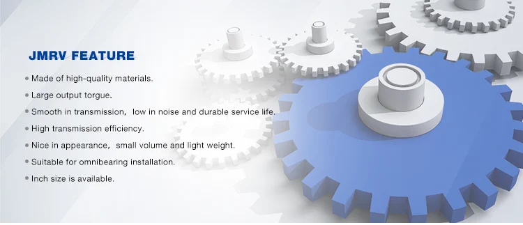
Professional manufacturers electric powered equipment motor with brake
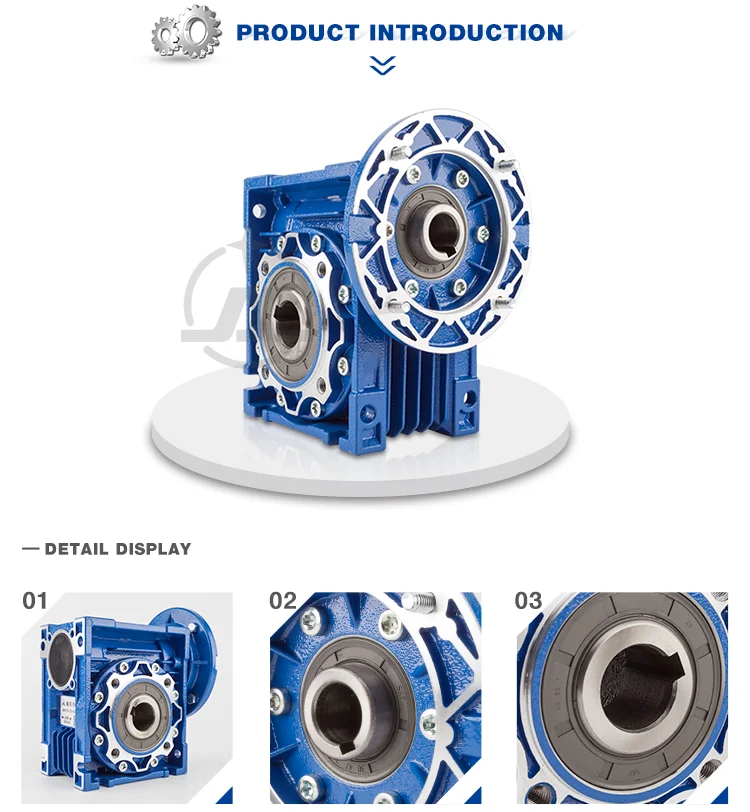
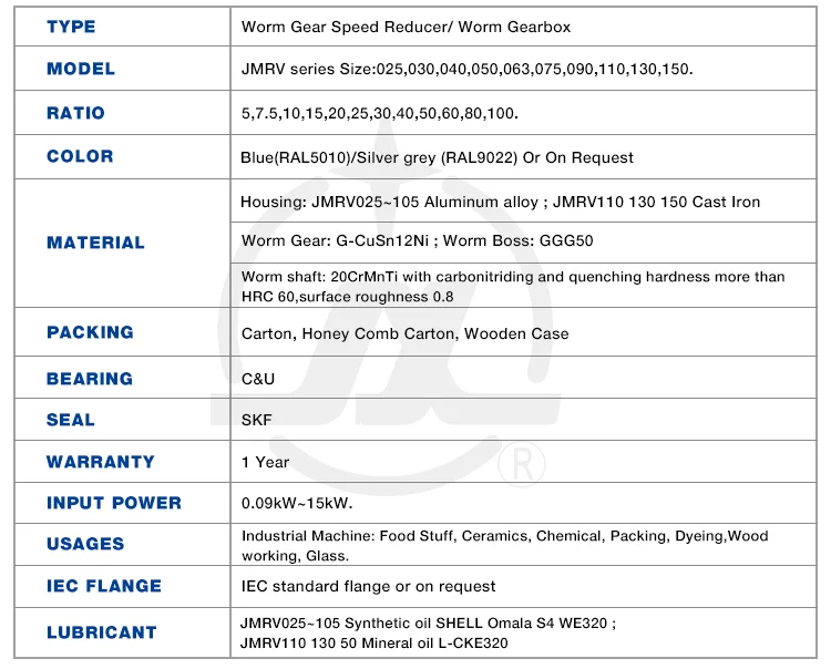
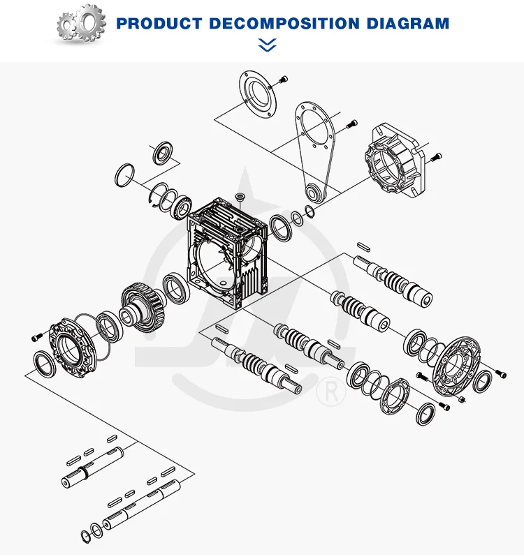
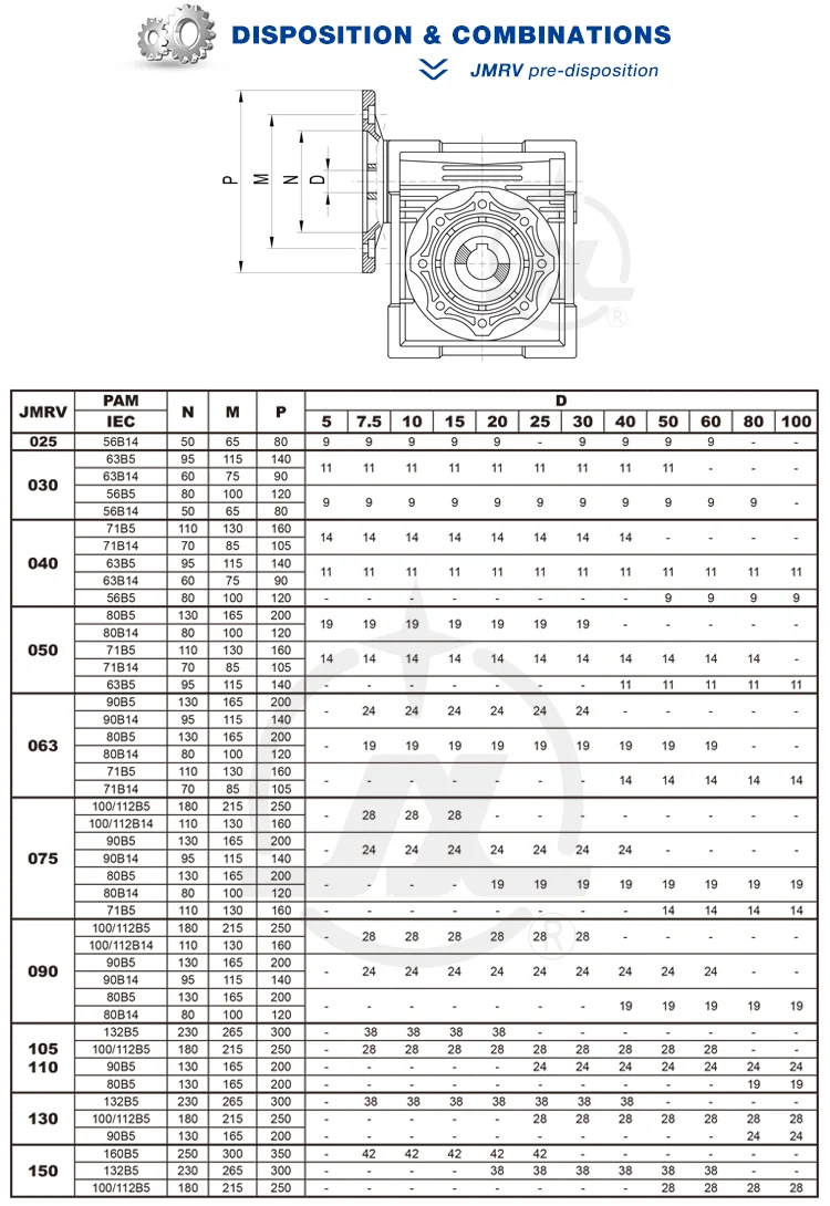


Q1. How to select a reduction motor which fulfills our necessity?
A1: You can refer to our catalogue to pick the gearbox or we can assist to pick when you offer
the technical data of output torque, output pace and motor parameter etc.
Q2. How is your price tag? Can you offer any price reduction?
A2: We will give the very best price we can base on your needs and the quantities.
Q3. Do you provide any visiting?
A3: Sure! We sincerely invite you to visit us! We can select you from airport, railway station and so on.
Also, we can prepare housing for you. Please enable us know in advanced.
This autumn. When is the very best time to get in touch with you?
A4: You can contact us by e mail any time, we will reply you as soon as achievable.
Q5. How lengthy will it consider for the direct time?
A5: For our common design, you should refer to the various item internet pages to check out the lead time.
For the OEM/ODM products, please make contact with us for additional details.