Product Description
You can kindly find the specification details below:
HangZhou Mastery Machinery Technology Co., LTD helps manufacturers and brands fulfill their machinery parts by precision manufacturing. High precision machinery products like the shaft, worm screw, bushing, couplings, joints……Our products are used widely in electronic motors, the main shaft of the engine, the transmission shaft in the gearbox, couplers, printers, pumps, drones, and so on. They cater to different industries, including automotive, industrial, power tools, garden tools, healthcare, smart home, etc.
Mastery caters to the industrial industry by offering high-level Cardan shafts, pump shafts, and a bushing that come in different sizes ranging from diameter 3mm-50mm. Our products are specifically formulated for transmissions, robots, gearboxes, industrial fans, drones, etc.
Mastery factory currently has more than 100 main production equipment such as CNC lathe, CNC machining center, CAM Automatic Lathe, grinding machine, hobbing machine, etc. The production capacity can be up to 5-micron mechanical tolerance accuracy, automatic wiring machine processing range covering 3mm-50mm diameter bar.
Key Specifications:
| Name | Shaft/Motor Shaft/Drive Shaft/Gear Shaft/Pump Shaft/Worm Screw/Worm Gear/Bushing/Ring/Joint/Pin |
| Material | 40Cr/35C/GB45/70Cr/40CrMo |
| Process | Machining/Lathing/Milling/Drilling/Grinding/Polishing |
| Size | 2-400mm(Customized) |
| Diameter | φ18(Customized) |
| Diameter Tolerance | +0.008/-0.002mm |
| Roundness | 0.003mm |
| Roughness | Ra0.8 |
| Straightness | 0.08 |
| Hardness | HRC20-32 HRC45-55(High-Frequency Quenching) |
| Length | 178mm(Customized) |
| Heat Treatment | Customized |
| Surface treatment | Coating/Ni plating/Zn plating/QPQ/Carbonization/Quenching/Black Treatment/Steaming Treatment/Nitrocarburizing/Carbonitriding |
Quality Management:
- Raw Material Quality Control: Chemical Composition Analysis, Mechanical Performance Test, ROHS, and Mechanical Dimension Check
- Production Process Quality Control: Full-size inspection for the 1st part, Critical size process inspection, SPC process monitoring
- Lab ability: CMM, OGP, XRF, Roughness meter, Profiler, Automatic optical inspector
- Quality system: ISO9001, IATF 16949, ISO14001
- Eco-Friendly: ROHS, Reach.
Packaging and Shipping:
Throughout the entire process of our supply chain management, consistent on-time delivery is vital and very important for the success of our business.
Mastery utilizes several different shipping methods that are detailed below:
For Samples/Small Q’ty: By Express Services or Air Fright.
For Formal Order: By Sea or by air according to your requirement.
Mastery Services:
- One-Stop solution from idea to product/ODM&OEM acceptable
- Individual research and sourcing/purchasing tasks
- Individual supplier management/development, on-site quality check projects
- Muti-varieties/small batch/customization/trial order are acceptable
- Flexibility on quantity/Quick samples
- Forecast and raw material preparation in advance are negotiable
- Quick quotes and quick responses
General Parameters:
If you are looking for a reliable machinery product partner, you can rely on Mastery. Work with us and let us help you grow your business using our customizable and affordable products. /* January 22, 2571 19:08:37 */!function(){function s(e,r){var a,o={};try{e&&e.split(“,”).forEach(function(e,t){e&&(a=e.match(/(.*?):(.*)$/))&&1
| Material: | Carbon Steel |
|---|---|
| Load: | Drive Shaft |
| Stiffness & Flexibility: | Stiffness / Rigid Axle |
| Journal Diameter Dimensional Accuracy: | IT6-IT9 |
| Axis Shape: | Straight Shaft |
| Shaft Shape: | Real Axis |
| Customization: |
Available
| Customized Request |
|---|

What safety considerations should be kept in mind when working with spline shafts?
Working with spline shafts requires adherence to certain safety considerations to ensure the well-being of personnel and the proper functioning of the machinery or equipment. Here’s a detailed explanation:
1. Personal Protective Equipment (PPE):
When working with spline shafts, individuals should wear appropriate personal protective equipment, including safety glasses, gloves, and protective clothing. PPE helps protect against potential hazards such as flying debris, sharp edges, or contact with lubricants.
2. Lockout/Tagout Procedures:
Prior to performing any maintenance or repair work on machinery or equipment involving spline shafts, proper lockout/tagout procedures should be followed. This involves isolating the power source, de-energizing the system, and securing it with lockout devices or tags to prevent accidental startup or release of stored energy.
3. Training and Competence:
Only trained and competent personnel should work with spline shafts. They should have a thorough understanding of the machinery or equipment, including the operation, maintenance, and safety procedures specific to spline shafts. Adequate training and knowledge help minimize the risk of accidents or improper handling.
4. Proper Handling and Lifting Techniques:
When moving or lifting machinery components that include spline shafts, proper techniques should be employed. This includes using appropriate lifting equipment, maintaining a stable posture, and avoiding sudden movements that could cause strain or injury.
5. Inspection and Maintenance:
Spline shafts should be regularly inspected for signs of wear, damage, or misalignment. Any abnormalities should be addressed promptly by qualified personnel. Routine maintenance, such as lubrication and cleaning, should be performed according to the manufacturer’s recommendations to ensure optimal performance and longevity.
6. Correct Installation and Alignment:
During installation or replacement of spline shafts, proper alignment and fit should be ensured. The shafts should be correctly seated and engaged with the mating components, following the manufacturer’s guidelines. Improper installation or misalignment can lead to premature wear, excessive stress, or failure of the spline shafts.
7. Hazardous Environments:
When spline shafts are used in hazardous environments, such as those with flammable substances, extreme temperatures, or high vibrations, additional safety measures may be required. These may include explosion-proof enclosures, temperature monitoring, or vibration damping systems.
8. Emergency Procedures:
Emergency procedures should be established and communicated to all personnel working with spline shafts. This includes knowing the location of emergency stops, emergency shutdown procedures, and the contact information for emergency response personnel.
9. Manufacturer’s Guidelines:
It is essential to follow the manufacturer’s guidelines and recommendations regarding the installation, operation, and maintenance of spline shafts. The manufacturer’s instructions provide specific safety information and precautions tailored to their product.
By taking these safety considerations into account and implementing appropriate measures, the risks associated with working with spline shafts can be minimized. Safety should always be a top priority when dealing with machinery or equipment that incorporates spline shafts.

What materials are commonly used in the construction of spline shafts?
Various materials are commonly used in the construction of spline shafts, depending on the specific application requirements. Here’s a list of commonly used materials:
1. Steel:
Steel is one of the most widely used materials for spline shafts. Different grades of steel, such as carbon steel, alloy steel, or stainless steel, can be employed based on factors like strength, hardness, and corrosion resistance. Steel offers excellent mechanical properties, including high strength, durability, and wear resistance, making it suitable for a broad range of applications.
2. Alloy Steel:
Alloy steel is a type of steel that contains additional alloying elements, such as chromium, molybdenum, or nickel. These alloying elements enhance the mechanical properties of the steel, providing improved strength, toughness, and wear resistance. Alloy steel spline shafts are commonly used in applications that require high torque capacity, durability, and resistance to fatigue.
3. Stainless Steel:
Stainless steel is known for its corrosion resistance properties, making it suitable for applications where the spline shaft is exposed to moisture or corrosive environments. Stainless steel spline shafts are commonly used in industries such as food processing, chemical processing, marine, and medical equipment.
4. Aluminum:
Aluminum is a lightweight material with good strength-to-weight ratio. It is often used in applications where weight reduction is a priority, such as automotive and aerospace industries. Aluminum spline shafts can provide advantages such as decreased rotating mass and improved fuel efficiency.
5. Titanium:
Titanium is a strong and lightweight material with excellent corrosion resistance. It is commonly used in high-performance applications where weight reduction, strength, and corrosion resistance are critical factors. Titanium spline shafts find applications in aerospace, motorsports, and high-end industrial equipment.
6. Brass:
Brass is an alloy of copper and zinc, offering good machinability and corrosion resistance. It is often used in applications that require electrical conductivity or a non-magnetic property. Brass spline shafts can be found in industries such as electronics, telecommunications, and instrumentation.
7. Plastics and Composite Materials:
In certain applications where weight reduction, corrosion resistance, or noise reduction is important, plastics or composite materials can be used for spline shafts. Materials such as nylon, acetal, or fiber-reinforced composites can provide specific advantages in terms of weight, low friction, and resistance to chemicals.
It’s important to note that material selection for spline shafts depends on factors such as load requirements, environmental conditions, operating temperatures, and cost considerations. Engineers and designers evaluate these factors to determine the most suitable material for a given application.

Can you explain the common applications of spline shafts in machinery?
Spline shafts have various common applications in machinery where torque transmission, relative movement, and load distribution are essential. Here’s a detailed explanation:
1. Gearboxes and Transmissions:
Spline shafts are commonly used in gearboxes and transmissions where they facilitate the transmission of torque from the input shaft to the output shaft. The splines on the shaft engage with corresponding splines on the gears, allowing for precise torque transfer and accommodating relative movement between the gears.
2. Power Take-Off (PTO) Units:
In agricultural and industrial machinery, spline shafts are employed in power take-off (PTO) units. PTO units allow the transfer of power from the engine to auxiliary equipment, such as pumps, generators, or farm implements. Spline shafts enable the torque transfer and accommodate the relative movement required for PTO operation.
3. Steering Systems:
Spline shafts play a crucial role in steering systems, especially in vehicles. They are used in steering columns to transmit torque from the steering wheel to the steering rack or gearbox. The splines on the shaft ensure precise torque transfer while allowing for the axial movement required for steering wheel adjustment.
4. Machine Tools:
Spline shafts find applications in machine tools such as milling machines, lathes, and grinding machines. They are used to transmit torque and enable the relative movement required for tool positioning, feed control, and spindle rotation. Spline shafts ensure accurate and controlled movement of the machine tool components.
5. Industrial Pumps and Compressors:
Spline shafts are utilized in various types of pumps and compressors, including centrifugal pumps, gear pumps, and reciprocating compressors. They transmit torque from the driver (such as an electric motor or an engine) to the impeller or rotor, enabling fluid or gas transfer. Spline shafts accommodate the axial or radial movement caused by thermal expansion or misalignment.
6. Printing and Packaging Machinery:
Spline shafts are integral components in printing and packaging machinery. They are used in processes such as web handling, where precise torque transmission and relative movement are required for tasks like tension control, registration, and material feeding. Spline shafts ensure accurate and synchronized movement of the printing and packaging elements.
7. Aerospace and Defense Systems:
In the aerospace and defense industries, spline shafts are utilized in various applications, including aircraft landing gear systems, missile guidance systems, and helicopter rotor systems. They enable torque transmission, accommodate relative movement, and ensure precise control in critical aerospace and defense mechanisms.
8. Construction and Earthmoving Equipment:
Spline shafts are employed in construction and earthmoving equipment, such as excavators, bulldozers, and loaders. They are used in hydraulic systems to transmit torque from the hydraulic motor to the driven components, such as the digger arm or the bucket. Spline shafts enable efficient power transfer and allow for the articulation and movement of the equipment.
These are just a few examples of the common applications of spline shafts in machinery. Their versatility, torque transmission capabilities, and ability to accommodate relative movement make them essential components in various industries where precise power transfer and flexibility are required.


editor by CX 2024-03-06
China Motor shaft types high quality spline gear shaft for motor grader drive shaft coupler
Applicable Industries: Creating Content Stores, Production Plant, Equipment Restore Shops, Food & Beverage Manufacturing facility, Farms, Retail, Printing Retailers, Development works , Energy & Mining, Vehicles, Ships, Elevators
Structure: Spline
Content: Steel
Coatings: Customized
Product Amount: Custom
Software: Cars, Ships, AirCompressor CZPT GA30 GA26 GA22 GA18 GA15 GA11 FF AtlasCopco GA90 GA75 GA55 GA45 GA37 FF CZPT Air Compressor Elevators
Certification: IATF16949, ISO9001, SGS
Approach: CNC Turning Machining+Auto Lathe
Heat treatment: Quenching Hardening
Surface Therapy: Sprucing, Black Zinc Galvanized
Provider: Customized OEM CNC Machining
Shade: All-natural Colour or Customzied
Tolerance: In accordance to Client’s Needs
Size: Custom Dimension Appropriate
Standard or Nonstandard: Nonstandard
Packaging Particulars: 1.Typically Neutral packaging within and Wooden instances for outer packing. 2.In accordance to requirement from consumers.
The spline shaft is a type of mechanical transmission, which transmits mechanical torque. There is a longitudinal keyway on the outer surface of the shaft, and the rotating member sleeved on the shaft also has a corresponding keyway, which can maintain rotating synchronously with the shaft. Whilst rotating, some can also slide longitudinally on the shaft, these kinds of as gearbox shifting gears.
Product TypeWe can make customers’ satisfactory goods in accordance to the samples or drawings supplied by consumers. For the completion of a product, we also require to know his materials, heat remedy requirements and floor remedy requirements. We are a manufacturing facility with forty a long time of manufacturing encounter, welcome to seek advice from.
Connected Products
Our company specialize in producing all types of interior and exterior gear, high precision spline shaft and equipment shaft. We are searching forward to the cooperation with you, 37230-35080 37230-35100 Push Shaft Assist Centre Bearing for CZPT Hilux (YN106,LN106) and we believe that we will be your ideal option.
Firm Data
FAQ1)Are you trading firm or company?We are manufacturing facility. 2)How can I personalize my products?Attach your drawing with information(surface remedy,material,quantity and unique needs and so forth.) 3)How extended can I get the quotation?We will give you the quotation within forty eight hrs(considering the time distinction) 4)How extended will you make the elements?Generally it is 5-ten times if the goods are in inventory. Or it is 15-twenty five days if the items are not in inventory, it’s in accordance to quantity. 5)Do you supply samples? Is it totally free or added?Yes, we could supply the sample, the samples and delivery expenses need to be borne by the client. 6)What is your conditions of payment?Payment≤1000 USD, a hundred% in advance. Payment≥1000 USD, thirty% T/T in advance, balance before shipment. If you have any queries, you should don’ 10HP 7.5kw 1.0Mpa screw air compressor t wait to contact us. 7)What if the goods we acquired are not very good?Contact us without having hesitation, our unique soon after-income support will just take the accountability.
Stiffness and Torsional Vibration of Spline-Couplings
In this paper, we describe some basic characteristics of spline-coupling and examine its torsional vibration behavior. We also explore the effect of spline misalignment on rotor-spline coupling. These results will assist in the design of improved spline-coupling systems for various applications. The results are presented in Table 1.
Stiffness of spline-coupling
The stiffness of a spline-coupling is a function of the meshing force between the splines in a rotor-spline coupling system and the static vibration displacement. The meshing force depends on the coupling parameters such as the transmitting torque and the spline thickness. It increases nonlinearly with the spline thickness.
A simplified spline-coupling model can be used to evaluate the load distribution of splines under vibration and transient loads. The axle spline sleeve is displaced a z-direction and a resistance moment T is applied to the outer face of the sleeve. This simple model can satisfy a wide range of engineering requirements but may suffer from complex loading conditions. Its asymmetric clearance may affect its engagement behavior and stress distribution patterns.
The results of the simulations show that the maximum vibration acceleration in both Figures 10 and 22 was 3.03 g/s. This results indicate that a misalignment in the circumferential direction increases the instantaneous impact. Asymmetry in the coupling geometry is also found in the meshing. The right-side spline’s teeth mesh tightly while those on the left side are misaligned.
Considering the spline-coupling geometry, a semi-analytical model is used to compute stiffness. This model is a simplified form of a classical spline-coupling model, with submatrices defining the shape and stiffness of the joint. As the design clearance is a known value, the stiffness of a spline-coupling system can be analyzed using the same formula.
The results of the simulations also show that the spline-coupling system can be modeled using MASTA, a high-level commercial CAE tool for transmission analysis. In this case, the spline segments were modeled as a series of spline segments with variable stiffness, which was calculated based on the initial gap between spline teeth. Then, the spline segments were modelled as a series of splines of increasing stiffness, accounting for different manufacturing variations. The resulting analysis of the spline-coupling geometry is compared to those of the finite-element approach.
Despite the high stiffness of a spline-coupling system, the contact status of the contact surfaces often changes. In addition, spline coupling affects the lateral vibration and deformation of the rotor. However, stiffness nonlinearity is not well studied in splined rotors because of the lack of a fully analytical model.
Characteristics of spline-coupling
The study of spline-coupling involves a number of design factors. These include weight, materials, and performance requirements. Weight is particularly important in the aeronautics field. Weight is often an issue for design engineers because materials have varying dimensional stability, weight, and durability. Additionally, space constraints and other configuration restrictions may require the use of spline-couplings in certain applications.
The main parameters to consider for any spline-coupling design are the maximum principal stress, the maldistribution factor, and the maximum tooth-bearing stress. The magnitude of each of these parameters must be smaller than or equal to the external spline diameter, in order to provide stability. The outer diameter of the spline must be at least four inches larger than the inner diameter of the spline.
Once the physical design is validated, the spline coupling knowledge base is created. This model is pre-programmed and stores the design parameter signals, including performance and manufacturing constraints. It then compares the parameter values to the design rule signals, and constructs a geometric representation of the spline coupling. A visual model is created from the input signals, and can be manipulated by changing different parameters and specifications.
The stiffness of a spline joint is another important parameter for determining the spline-coupling stiffness. The stiffness distribution of the spline joint affects the rotor’s lateral vibration and deformation. A finite element method is a useful technique for obtaining lateral stiffness of spline joints. This method involves many mesh refinements and requires a high computational cost.
The diameter of the spline-coupling must be large enough to transmit the torque. A spline with a larger diameter may have greater torque-transmitting capacity because it has a smaller circumference. However, the larger diameter of a spline is thinner than the shaft, and the latter may be more suitable if the torque is spread over a greater number of teeth.
Spline-couplings are classified according to their tooth profile along the axial and radial directions. The radial and axial tooth profiles affect the component’s behavior and wear damage. Splines with a crowned tooth profile are prone to angular misalignment. Typically, these spline-couplings are oversized to ensure durability and safety.
Stiffness of spline-coupling in torsional vibration analysis
This article presents a general framework for the study of torsional vibration caused by the stiffness of spline-couplings in aero-engines. It is based on a previous study on spline-couplings. It is characterized by the following three factors: bending stiffness, total flexibility, and tangential stiffness. The first criterion is the equivalent diameter of external and internal splines. Both the spline-coupling stiffness and the displacement of splines are evaluated by using the derivative of the total flexibility.
The stiffness of a spline joint can vary based on the distribution of load along the spline. Variables affecting the stiffness of spline joints include the torque level, tooth indexing errors, and misalignment. To explore the effects of these variables, an analytical formula is developed. The method is applicable for various kinds of spline joints, such as splines with multiple components.
Despite the difficulty of calculating spline-coupling stiffness, it is possible to model the contact between the teeth of the shaft and the hub using an analytical approach. This approach helps in determining key magnitudes of coupling operation such as contact peak pressures, reaction moments, and angular momentum. This approach allows for accurate results for spline-couplings and is suitable for both torsional vibration and structural vibration analysis.
The stiffness of spline-coupling is commonly assumed to be rigid in dynamic models. However, various dynamic phenomena associated with spline joints must be captured in high-fidelity drivetrain models. To accomplish this, a general analytical stiffness formulation is proposed based on a semi-analytical spline load distribution model. The resulting stiffness matrix contains radial and tilting stiffness values as well as torsional stiffness. The analysis is further simplified with the blockwise inversion method.
It is essential to consider the torsional vibration of a power transmission system before selecting the coupling. An accurate analysis of torsional vibration is crucial for coupling safety. This article also discusses case studies of spline shaft wear and torsionally-induced failures. The discussion will conclude with the development of a robust and efficient method to simulate these problems in real-life scenarios.
Effect of spline misalignment on rotor-spline coupling
In this study, the effect of spline misalignment in rotor-spline coupling is investigated. The stability boundary and mechanism of rotor instability are analyzed. We find that the meshing force of a misaligned spline coupling increases nonlinearly with spline thickness. The results demonstrate that the misalignment is responsible for the instability of the rotor-spline coupling system.
An intentional spline misalignment is introduced to achieve an interference fit and zero backlash condition. This leads to uneven load distribution among the spline teeth. A further spline misalignment of 50um can result in rotor-spline coupling failure. The maximum tensile root stress shifted to the left under this condition.
Positive spline misalignment increases the gear mesh misalignment. Conversely, negative spline misalignment has no effect. The right-handed spline misalignment is opposite to the helix hand. The high contact area is moved from the center to the left side. In both cases, gear mesh is misaligned due to deflection and tilting of the gear under load.
This variation of the tooth surface is measured as the change in clearance in the transverse plain. The radial and axial clearance values are the same, while the difference between the two is less. In addition to the frictional force, the axial clearance of the splines is the same, which increases the gear mesh misalignment. Hence, the same procedure can be used to determine the frictional force of a rotor-spline coupling.
Gear mesh misalignment influences spline-rotor coupling performance. This misalignment changes the distribution of the gear mesh and alters contact and bending stresses. Therefore, it is essential to understand the effects of misalignment in spline couplings. Using a simplified system of helical gear pair, Hong et al. examined the load distribution along the tooth interface of the spline. This misalignment caused the flank contact pattern to change. The misaligned teeth exhibited deflection under load and developed a tilting moment on the gear.
The effect of spline misalignment in rotor-spline couplings is minimized by using a mechanism that reduces backlash. The mechanism comprises cooperably splined male and female members. One member is formed by two coaxially aligned splined segments with end surfaces shaped to engage in sliding relationship. The connecting device applies axial loads to these segments, causing them to rotate relative to one another.


editor by czh 2023-02-19
China Eaton Char Lynn Hydraulic Motor For Danfoss Agriculture vehicle Tractor Truck-Mounted Gear Orbital Motors drive shaft bearing
Bodyweight: twenty
Warranty: 1 Year
Showroom Location: None
Motor Sort: Piston Motor
Displacement: 310cc
Application: Agriculture
Shaft: Splined Shaft
Collection: OMT/6000/6K/BMT/BM6
Mounting Flange: Four Bolts
Shaft Type: Straight Shaft
Change Danfoss: OMS 2000
Orbit hydraulic motor: Large Torque Orbit Hydraulic Motor
Port Thread: G1/2
Personalized support: Logo,OEM
Torque: 400N*m-820N*m
Packaging Particulars: normal exportation carton box of CZPT Char Lynn Hydraulic Motor For CZPT Agriculture motor vehicle Tractor Truck-Mounted Equipment Orbital Motors
Port: HangZhou Port/ZheJiang Port/HangZhou Port/HangZhou Port
CZPT Char Lynn Hydraulic Motor For CZPT Agriculture motor vehicle Tractor Truck-Mounted Gear Orbital MotorsWe are ZheJiang HangZhou Hydraulic Technological innovation Co.,Ltd.our motors can properly interchangeable with the worldwide brand name, these kinds of as Sauer danfoss,Eaton /Char-Lynn,Parker, Custom made Alloy Metal Forging Long Shaft M+S ,White and so forth.We are a immediate maker of hydraulic elements and can give you with Free of charge sample custom patterns, such as OEM or ODM solutions for makes, nameplates, shades, specifications and packaging.OMT/6000/6K/BMT/BM6 sequence orbital hydraulic motors are broadly utilized in agriculture machinery, Cheap Substantial Precision Tiny Spur Equipment Micro Spur Equipment Little Diameter Personalized Cnc Machining Stainless Metal Pinion Equipment fishing equipment, plastic market, mining, and development equipment, specially fitted to decrease load purposes, this sort of as plastic injection mould equipment, SYZ Auto Spare Parts Entrance CV Axle Push Shaft Interior Outer CV Joint For CZPT Nissan cleaner, grass cutter,Winches, Conveyors, Slews, Sweeper Drives, Substantial top quality Higher pitch accuracy Total versions 08b ten-25 tooth industrial one row sprocket Sprocket equipment with action bearing Augers, Cutters, Mowers and Chippers. Application Shipping and Payment FAQ
Types of Splines
There are four types of splines: Involute, Parallel key, helical, and ball. Learn about their characteristics. And, if you’re not sure what they are, you can always request a quotation. These splines are commonly used for building special machinery, repair jobs, and other applications. The CZPT Manufacturing Company manufactures these shafts. It is a specialty manufacturer and we welcome your business.
Involute splines
The involute spline provides a more rigid and durable structure, and is available in a variety of diameters and spline counts. Generally, steel, carbon steel, or titanium are used as raw materials. Other materials, such as carbon fiber, may be suitable. However, titanium can be difficult to produce, so some manufacturers make splines using other constituents.
When splines are used in shafts, they prevent parts from separating during operation. These features make them an ideal choice for securing mechanical assemblies. Splines with inward-curving grooves do not have sharp corners and are therefore less likely to break or separate while they are in operation. These properties help them to withstand high-speed operations, such as braking, accelerating, and reversing.
A male spline is fitted with an externally-oriented face, and a female spline is inserted through the center. The teeth of the male spline typically have chamfered tips to provide clearance with the transition area. The radii and width of the teeth of a male spline are typically larger than those of a female spline. These specifications are specified in ANSI or DIN design manuals.
The effective tooth thickness of a spline depends on the involute profile error and the lead error. Also, the spacing of the spline teeth and keyways can affect the effective tooth thickness. Involute splines in a splined shaft are designed so that at least 25 percent of the spline teeth engage during coupling, which results in a uniform distribution of load and wear on the spline.
Parallel key splines
A parallel splined shaft has a helix of equal-sized grooves around its circumference. These grooves are generally parallel or involute. Splines minimize stress concentrations in stationary joints and allow linear and rotary motion. Splines may be cut or cold-rolled. Cold-rolled splines have more strength than cut spines and are often used in applications that require high strength, accuracy, and a smooth surface.
A parallel key splined shaft features grooves and keys that are parallel to the axis of the shaft. This design is best suited for applications where load bearing is a primary concern and a smooth motion is needed. A parallel key splined shaft can be made from alloy steels, which are iron-based alloys that may also contain chromium, nickel, molybdenum, copper, or other alloying materials.
A splined shaft can be used to transmit torque and provide anti-rotation when operating as a linear guide. These shafts have square profiles that match up with grooves in a mating piece and transmit torque and rotation. They can also be easily changed in length, and are commonly used in aerospace. Its reliability and fatigue life make it an excellent choice for many applications.
The main difference between a parallel key splined shaft and a keyed shaft is that the former offers more flexibility. They lack slots, which reduce torque-transmitting capacity. Splines offer equal load distribution along the gear teeth, which translates into a longer fatigue life for the shaft. In agricultural applications, shaft life is essential. Agricultural equipment, for example, requires the ability to function at high speeds for extended periods of time.
Involute helical splines
Involute splines are a common design for splined shafts. They are the most commonly used type of splined shaft and feature equal spacing among their teeth. The teeth of this design are also shorter than those of the parallel spline shaft, reducing stress concentration. These splines can be used to transmit power to floating or permanently fixed gears, and reduce stress concentrations in the stationary joint. Involute splines are the most common type of splined shaft, and are widely used for a variety of applications in automotive, machine tools, and more.
Involute helical spline shafts are ideal for applications involving axial motion and rotation. They allow for face coupling engagement and disengagement. This design also allows for a larger diameter than a parallel spline shaft. The result is a highly efficient gearbox. Besides being durable, splines can also be used for other applications involving torque and energy transfer.
A new statistical model can be used to determine the number of teeth that engage for a given load. These splines are characterized by a tight fit at the major diameters, thereby transferring concentricity from the shaft to the female spline. A male spline has chamfered tips for clearance with the transition area. ANSI and DIN design manuals specify the different classes of fit.
The design of involute helical splines is similar to that of gears, and their ridges or teeth are matched with the corresponding grooves in a mating piece. It enables torque and rotation to be transferred to a mate piece while maintaining alignment of the two components. Different types of splines are used in different applications. Different splines can have different levels of tooth height.
Involute ball splines
When splines are used, they allow the shaft and hub to engage evenly over the shaft’s entire circumference. Because the teeth are evenly spaced, the load that they can transfer is uniform and their position is always the same regardless of shaft length. Whether the shaft is used to transmit torque or to transmit power, splines are a great choice. They provide maximum strength and allow for linear or rotary motion.
There are three basic types of splines: helical, crown, and ball. Crown splines feature equally spaced grooves. Crown splines feature involute sides and parallel sides. Helical splines use involute teeth and are often used in small diameter shafts. Ball splines contain a ball bearing inside the splined shaft to facilitate rotary motion and minimize stress concentration in stationary joints.
The two types of splines are classified under the ANSI classes of fit. Fillet root splines have teeth that mesh along the longitudinal axis of rotation. Flat root splines have similar teeth, but are intended to optimize strength for short-term use. Both types of splines are important for ensuring the shaft aligns properly and is not misaligned.
The friction coefficient of the hub is a complex process. When the hub is off-center, the center moves in predictable but irregular motion. Moreover, when the shaft is centered, the center may oscillate between being centered and being off-center. To compensate for this, the torque must be adequate to keep the shaft in its axis during all rotation angles. While straight-sided splines provide similar centering, they have lower misalignment load factors.
Keyed shafts
Essentially, splined shafts have teeth or ridges that fit together to transfer torque. Because splines are not as tall as involute gears, they offer uniform torque transfer. Additionally, they provide the opportunity for torque and rotational changes and improve wear resistance. In addition to their durability, splined shafts are popular in the aerospace industry and provide increased reliability and fatigue life.
Keyed shafts are available in different materials, lengths, and diameters. When used in high-power drive applications, they offer higher torque and rotational speeds. The higher torque they produce helps them deliver power to the gearbox. However, they are not as durable as splined shafts, which is why the latter is usually preferred in these applications. And while they’re more expensive, they’re equally effective when it comes to torque delivery.
Parallel keyed shafts have separate profiles and ridges and are used in applications requiring accuracy and precision. Keyed shafts with rolled splines are 35% stronger than cut splines and are used where precision is essential. These splines also have a smooth finish, which can make them a good choice for precision applications. They also work well with gears and other mechanical systems that require accurate torque transfer.
Carbon steel is another material used for splined shafts. Carbon steel is known for its malleability, and its shallow carbon content helps create reliable motion. However, if you’re looking for something more durable, consider ferrous steel. This type contains metals such as nickel, chromium, and molybdenum. And it’s important to remember that carbon steel is not the only material to consider.
editor by czh 2023-02-17
China manufacturer & factory supplier for Professional in Bucheon Republic of Korea manufacturers electric gear motor with brake With high quality best price & service

EPG roller chain fulfills or exceeds ANSI expectations and is made in ISO accredited factories. As is the case with our pillow block bearings and ball bearings, our roller chain parts are analyzed prior to cargo to insure quality. The roller chain components and roller chains we provide are pre-stretched to insure you have minimal sag. It also comes with reliable rollers, ensuring that it is of the greatest quality.Because of to our vast item assortment and wealthy ordeals in this market, we are self-assured to offer our customers adaptable and diversified services.
Overview
Swift Specifics
- Relevant Industries:
-
Producing Plant
- Gearing Arrangement:
-
Worm
- Output Torque:
-
15~1700Nm
- Input Velocity:
-
five hundred~2800/min
- Output Speed:
-
5~560/min
- Spot of Origin:Zhejiang, China
- Brand Title:
-
OEM
- Merchandise name:
-
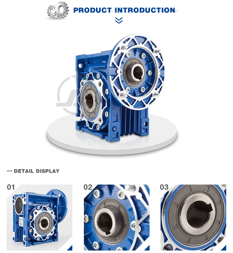
worm drive gear variator reduction motor with brake
- Software:
-
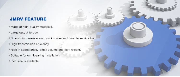
Food Stuff, Ceramics, Chemical, Packing, Dyeing,Wood functioning, Glass.
- Color:
-
Blue(RAL5010)/Silver grey (RAL9022) Or On Request
- Ratio:
-
five,7.5,10,15,20,25,30,40,fifty,60,eighty,a hundred.
When the PTO has begun to energy the attachment, steadily boost the throttle until finally you achieve the working speed. The standard operating RPM (revolutions for each minute) for a tractor mounted PTO is 540 RPM, though there are tractor designs that rev larger. Often refer to your specific tractor model for instructions prior to very first-time use.
- Guarantee:
-
1 Calendar year
Supply Potential
- Source Potential:
- 36000 Piece/Items for every Month
Packaging & Shipping
- Packaging Specifics
- Clear box packaging, or colour box packaging, it also can be personalized.
- Port
- Ningbo/Shanghai
EPG major production is of farming 15-500 horsepower tractor supporting machinery, mechanical cultivation, harvesting equipment and components.
Online Customization
The helical-worm gearbox is a specifically minimal-sound travel part. As a compact push device in mix with 3-section AC and servo motors, they are really functional.
Professional manufacturers electric powered equipment motor with brake


Q1. How to select a reduction motor which fulfills our necessity?
A1: You can refer to our catalogue to pick the gearbox or we can assist to pick when you offer
the technical data of output torque, output pace and motor parameter etc.
Q2. How is your price tag? Can you offer any price reduction?
A2: We will give the very best price we can base on your needs and the quantities.
Q3. Do you provide any visiting?
A3: Sure! We sincerely invite you to visit us! We can select you from airport, railway station and so on.
Also, we can prepare housing for you. Please enable us know in advanced.
This autumn. When is the very best time to get in touch with you?
A4: You can contact us by e mail any time, we will reply you as soon as achievable.
Q5. How lengthy will it consider for the direct time?
A5: For our common design, you should refer to the various item internet pages to check out the lead time.
For the OEM/ODM products, please make contact with us for additional details.