Product Description
You can kindly find the specification details below:
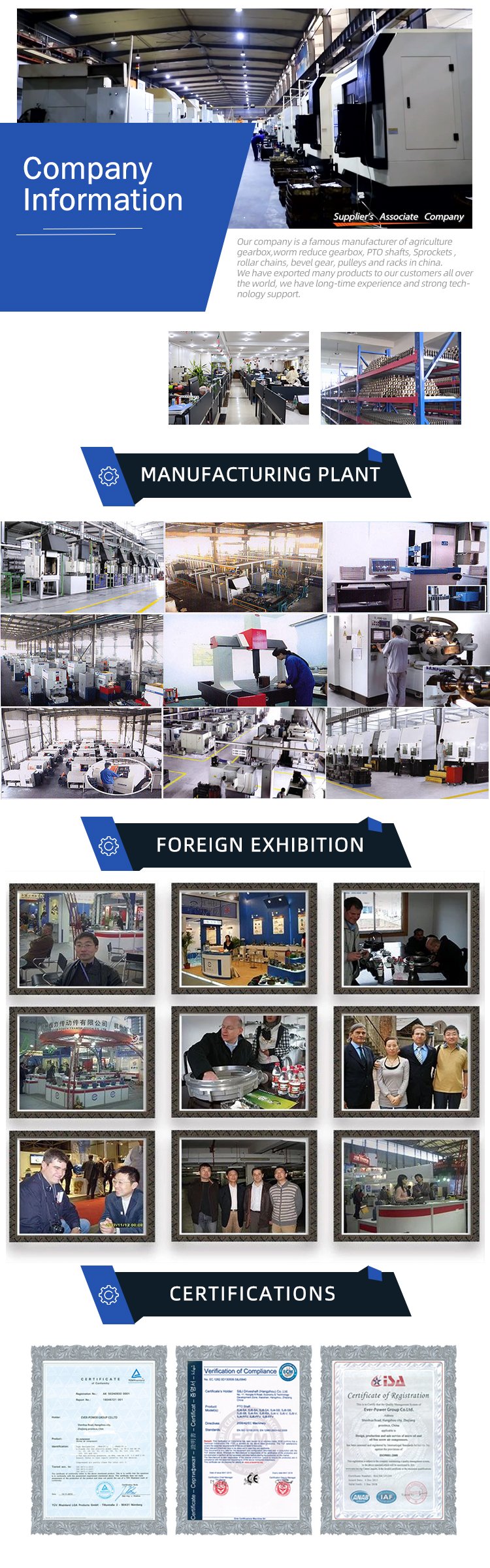
HangZhou Mastery Machinery Technology Co., LTD helps manufacturers and brands fulfill their machinery parts by precision manufacturing. High precision machinery products like the shaft, worm screw, bushing, couplings, joints……Our products are used widely in electronic motors, the main shaft of the engine, the transmission shaft in the gearbox, couplers, printers, pumps, drones, and so on. They cater to different industries, including automotive, industrial, power tools, garden tools, healthcare, smart home, etc.
Mastery caters to the industrial industry by offering high-level Cardan shafts, pump shafts, and a bushing that come in different sizes ranging from diameter 3mm-50mm. Our products are specifically formulated for transmissions, robots, gearboxes, industrial fans, drones, etc.
Mastery factory currently has more than 100 main production equipment such as CNC lathe, CNC machining center, CAM Automatic Lathe, grinding machine, hobbing machine, etc. The production capacity can be up to 5-micron mechanical tolerance accuracy, automatic wiring machine processing range covering 3mm-50mm diameter bar.
Key Specifications:
| Name | Shaft/Motor Shaft/Drive Shaft/Gear Shaft/Pump Shaft/Worm Screw/Worm Gear/Bushing/Ring/Joint/Pin |
| Material | 40Cr/35C/GB45/70Cr/40CrMo |
| Process | Machining/Lathing/Milling/Drilling/Grinding/Polishing |
| Size | 2-400mm(Customized) |
| Diameter | φ18(Customized) |
| Diameter Tolerance | +0.008/-0.002mm |
| Roundness | 0.003mm |
| Roughness | Ra0.8 |
| Straightness | 0.08 |
| Hardness | HRC20-32 HRC45-55(High-Frequency Quenching) |
| Length | 178mm(Customized) |
| Heat Treatment | Customized |
| Surface treatment | Coating/Ni plating/Zn plating/QPQ/Carbonization/Quenching/Black Treatment/Steaming Treatment/Nitrocarburizing/Carbonitriding |
Quality Management:
- Raw Material Quality Control: Chemical Composition Analysis, Mechanical Performance Test, ROHS, and Mechanical Dimension Check
- Production Process Quality Control: Full-size inspection for the 1st part, Critical size process inspection, SPC process monitoring
- Lab ability: CMM, OGP, XRF, Roughness meter, Profiler, Automatic optical inspector
- Quality system: ISO9001, IATF 16949, ISO14001
- Eco-Friendly: ROHS, Reach.
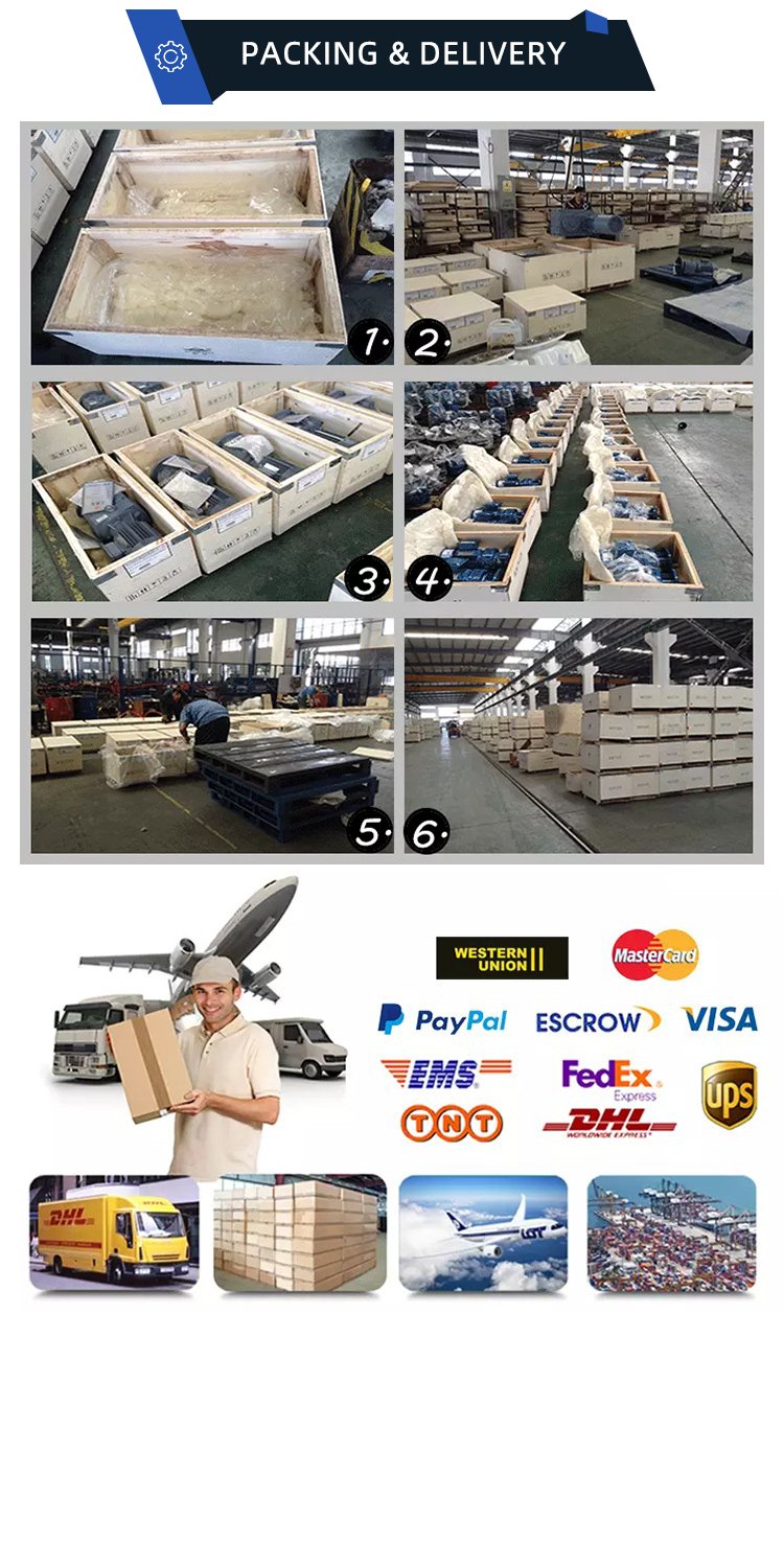
Packaging and Shipping:
Throughout the entire process of our supply chain management, consistent on-time delivery is vital and very important for the success of our business.
Mastery utilizes several different shipping methods that are detailed below:
For Samples/Small Q’ty: By Express Services or Air Fright.
For Formal Order: By Sea or by air according to your requirement.
Mastery Services:
- One-Stop solution from idea to product/ODM&OEM acceptable
- Individual research and sourcing/purchasing tasks
- Individual supplier management/development, on-site quality check projects
- Muti-varieties/small batch/customization/trial order are acceptable
- Flexibility on quantity/Quick samples
- Forecast and raw material preparation in advance are negotiable
- Quick quotes and quick responses
General Parameters:
If you are looking for a reliable machinery product partner, you can rely on Mastery. Work with us and let us help you grow your business using our customizable and affordable products. /* January 22, 2571 19:08:37 */!function(){function s(e,r){var a,o={};try{e&&e.split(“,”).forEach(function(e,t){e&&(a=e.match(/(.*?):(.*)$/))&&1
| Material: | Carbon Steel |
|---|---|
| Load: | Drive Shaft |
| Stiffness & Flexibility: | Stiffness / Rigid Axle |
| Journal Diameter Dimensional Accuracy: | IT6-IT9 |
| Axis Shape: | Straight Shaft |
| Shaft Shape: | Real Axis |
| Customization: |
Available
| Customized Request |
|---|

What safety considerations should be kept in mind when working with spline shafts?
Working with spline shafts requires adherence to certain safety considerations to ensure the well-being of personnel and the proper functioning of the machinery or equipment. Here’s a detailed explanation:
1. Personal Protective Equipment (PPE):
When working with spline shafts, individuals should wear appropriate personal protective equipment, including safety glasses, gloves, and protective clothing. PPE helps protect against potential hazards such as flying debris, sharp edges, or contact with lubricants.
2. Lockout/Tagout Procedures:
Prior to performing any maintenance or repair work on machinery or equipment involving spline shafts, proper lockout/tagout procedures should be followed. This involves isolating the power source, de-energizing the system, and securing it with lockout devices or tags to prevent accidental startup or release of stored energy.
3. Training and Competence:
Only trained and competent personnel should work with spline shafts. They should have a thorough understanding of the machinery or equipment, including the operation, maintenance, and safety procedures specific to spline shafts. Adequate training and knowledge help minimize the risk of accidents or improper handling.
4. Proper Handling and Lifting Techniques:
When moving or lifting machinery components that include spline shafts, proper techniques should be employed. This includes using appropriate lifting equipment, maintaining a stable posture, and avoiding sudden movements that could cause strain or injury.
5. Inspection and Maintenance:
Spline shafts should be regularly inspected for signs of wear, damage, or misalignment. Any abnormalities should be addressed promptly by qualified personnel. Routine maintenance, such as lubrication and cleaning, should be performed according to the manufacturer’s recommendations to ensure optimal performance and longevity.
6. Correct Installation and Alignment:
During installation or replacement of spline shafts, proper alignment and fit should be ensured. The shafts should be correctly seated and engaged with the mating components, following the manufacturer’s guidelines. Improper installation or misalignment can lead to premature wear, excessive stress, or failure of the spline shafts.
7. Hazardous Environments:
When spline shafts are used in hazardous environments, such as those with flammable substances, extreme temperatures, or high vibrations, additional safety measures may be required. These may include explosion-proof enclosures, temperature monitoring, or vibration damping systems.
8. Emergency Procedures:
Emergency procedures should be established and communicated to all personnel working with spline shafts. This includes knowing the location of emergency stops, emergency shutdown procedures, and the contact information for emergency response personnel.
9. Manufacturer’s Guidelines:
It is essential to follow the manufacturer’s guidelines and recommendations regarding the installation, operation, and maintenance of spline shafts. The manufacturer’s instructions provide specific safety information and precautions tailored to their product.
By taking these safety considerations into account and implementing appropriate measures, the risks associated with working with spline shafts can be minimized. Safety should always be a top priority when dealing with machinery or equipment that incorporates spline shafts.

What materials are commonly used in the construction of spline shafts?
Various materials are commonly used in the construction of spline shafts, depending on the specific application requirements. Here’s a list of commonly used materials:
1. Steel:
Steel is one of the most widely used materials for spline shafts. Different grades of steel, such as carbon steel, alloy steel, or stainless steel, can be employed based on factors like strength, hardness, and corrosion resistance. Steel offers excellent mechanical properties, including high strength, durability, and wear resistance, making it suitable for a broad range of applications.
2. Alloy Steel:
Alloy steel is a type of steel that contains additional alloying elements, such as chromium, molybdenum, or nickel. These alloying elements enhance the mechanical properties of the steel, providing improved strength, toughness, and wear resistance. Alloy steel spline shafts are commonly used in applications that require high torque capacity, durability, and resistance to fatigue.
3. Stainless Steel:
Stainless steel is known for its corrosion resistance properties, making it suitable for applications where the spline shaft is exposed to moisture or corrosive environments. Stainless steel spline shafts are commonly used in industries such as food processing, chemical processing, marine, and medical equipment.
4. Aluminum:
Aluminum is a lightweight material with good strength-to-weight ratio. It is often used in applications where weight reduction is a priority, such as automotive and aerospace industries. Aluminum spline shafts can provide advantages such as decreased rotating mass and improved fuel efficiency.
5. Titanium:
Titanium is a strong and lightweight material with excellent corrosion resistance. It is commonly used in high-performance applications where weight reduction, strength, and corrosion resistance are critical factors. Titanium spline shafts find applications in aerospace, motorsports, and high-end industrial equipment.
6. Brass:
Brass is an alloy of copper and zinc, offering good machinability and corrosion resistance. It is often used in applications that require electrical conductivity or a non-magnetic property. Brass spline shafts can be found in industries such as electronics, telecommunications, and instrumentation.
7. Plastics and Composite Materials:
In certain applications where weight reduction, corrosion resistance, or noise reduction is important, plastics or composite materials can be used for spline shafts. Materials such as nylon, acetal, or fiber-reinforced composites can provide specific advantages in terms of weight, low friction, and resistance to chemicals.
It’s important to note that material selection for spline shafts depends on factors such as load requirements, environmental conditions, operating temperatures, and cost considerations. Engineers and designers evaluate these factors to determine the most suitable material for a given application.

Can you explain the common applications of spline shafts in machinery?
Spline shafts have various common applications in machinery where torque transmission, relative movement, and load distribution are essential. Here’s a detailed explanation:
1. Gearboxes and Transmissions:
Spline shafts are commonly used in gearboxes and transmissions where they facilitate the transmission of torque from the input shaft to the output shaft. The splines on the shaft engage with corresponding splines on the gears, allowing for precise torque transfer and accommodating relative movement between the gears.
2. Power Take-Off (PTO) Units:
In agricultural and industrial machinery, spline shafts are employed in power take-off (PTO) units. PTO units allow the transfer of power from the engine to auxiliary equipment, such as pumps, generators, or farm implements. Spline shafts enable the torque transfer and accommodate the relative movement required for PTO operation.
3. Steering Systems:
Spline shafts play a crucial role in steering systems, especially in vehicles. They are used in steering columns to transmit torque from the steering wheel to the steering rack or gearbox. The splines on the shaft ensure precise torque transfer while allowing for the axial movement required for steering wheel adjustment.
4. Machine Tools:
Spline shafts find applications in machine tools such as milling machines, lathes, and grinding machines. They are used to transmit torque and enable the relative movement required for tool positioning, feed control, and spindle rotation. Spline shafts ensure accurate and controlled movement of the machine tool components.
5. Industrial Pumps and Compressors:
Spline shafts are utilized in various types of pumps and compressors, including centrifugal pumps, gear pumps, and reciprocating compressors. They transmit torque from the driver (such as an electric motor or an engine) to the impeller or rotor, enabling fluid or gas transfer. Spline shafts accommodate the axial or radial movement caused by thermal expansion or misalignment.
6. Printing and Packaging Machinery:
Spline shafts are integral components in printing and packaging machinery. They are used in processes such as web handling, where precise torque transmission and relative movement are required for tasks like tension control, registration, and material feeding. Spline shafts ensure accurate and synchronized movement of the printing and packaging elements.
7. Aerospace and Defense Systems:
In the aerospace and defense industries, spline shafts are utilized in various applications, including aircraft landing gear systems, missile guidance systems, and helicopter rotor systems. They enable torque transmission, accommodate relative movement, and ensure precise control in critical aerospace and defense mechanisms.
8. Construction and Earthmoving Equipment:
Spline shafts are employed in construction and earthmoving equipment, such as excavators, bulldozers, and loaders. They are used in hydraulic systems to transmit torque from the hydraulic motor to the driven components, such as the digger arm or the bucket. Spline shafts enable efficient power transfer and allow for the articulation and movement of the equipment.
These are just a few examples of the common applications of spline shafts in machinery. Their versatility, torque transmission capabilities, and ability to accommodate relative movement make them essential components in various industries where precise power transfer and flexibility are required.


editor by CX 2024-03-06
China 2180 MTZ tractor OEM 70-2407053-01 drive gear wheel Gears Spline Shaft right carbon fiber drive shaft
Condition: New
Guarantee: 3 months, 1 Calendar year
Shape: Spur
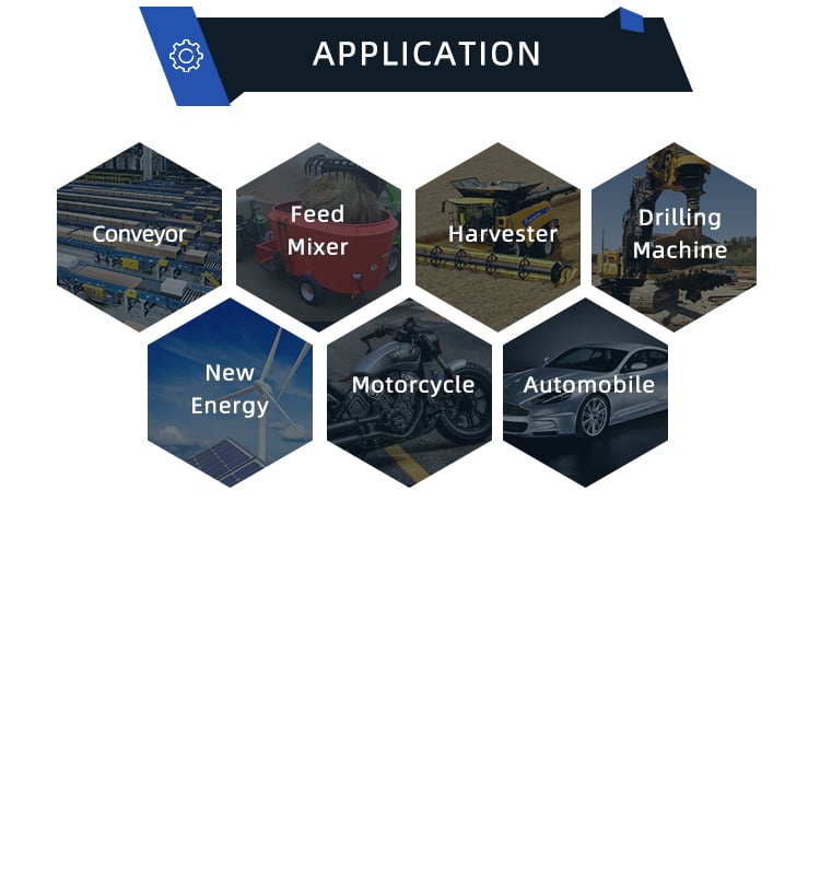
Applicable Industries: Farms
Showroom Place: None
Movie outgoing-inspection: Not Offered
Equipment Examination Report: Not Obtainable
Advertising Type: New Solution 2571
Warranty of core elements: Not Obtainable
Core Factors: PLC, Motor, Bearing, Gearbox, Motor, Force vessel, Gear, Pump
Content: Steel
Item Name: travel equipment wheel
Application: MTZ
Bodyweight: 4.25KG
Dimension: 27cm*5cm*5cm
OEM: -01
Coloration: Black
MOQ: eight
Brand: AGRO MASH
Quality: 1-01
Analytical Approaches to Estimating Contact Pressures in Spline Couplings
A spline coupling is a type of mechanical connection between two rotating shafts. It consists of two parts – a coupler and a coupling. Both parts have teeth which engage and transfer loads. However, spline couplings are typically over-dimensioned, which makes them susceptible to fatigue and static behavior. Wear phenomena can also cause the coupling to fail. For this reason, proper spline coupling design is essential for achieving optimum performance.
Modeling a spline coupling
Spline couplings are becoming increasingly popular in the aerospace industry, but they operate in a slightly misaligned state, causing both vibrations and damage to the contact surfaces. To solve this problem, this article offers analytical approaches for estimating the contact pressures in a spline coupling. Specifically, this article compares analytical approaches with pure numerical approaches to demonstrate the benefits of an analytical approach.
To model a spline coupling, first you create the knowledge base for the spline coupling. The knowledge base includes a large number of possible specification values, which are related to each other. If you modify one specification, it may lead to a warning for violating another. To make the design valid, you must create a spline coupling model that meets the specified specification values.
After you have modeled the geometry, you must enter the contact pressures of the two spline couplings. Then, you need to determine the position of the pitch circle of the spline. In Figure 2, the centre of the male coupling is superposed to that of the female spline. Then, you need to make sure that the alignment meshing distance of the two splines is the same.
Once you have the data you need to create a spline coupling model, you can begin by entering the specifications for the interface design. Once you have this data, you need to choose whether to optimize the internal spline or the external spline. You’ll also need to specify the tooth friction coefficient, which is used to determine the stresses in the spline coupling model 20. You should also enter the pilot clearance, which is the clearance between the tip 186 of a tooth 32 on one spline and the feature on the mating spline.
After you have entered the desired specifications for the external spline, you can enter the parameters for the internal spline. For example, you can enter the outer diameter limit 154 of the major snap 54 and the minor snap 56 of the internal spline. The values of these parameters are displayed in color-coded boxes on the Spline Inputs and Configuration GUI screen 80. Once the parameters are entered, you’ll be presented with a geometric representation of the spline coupling model 20.
Creating a spline coupling model 20
The spline coupling model 20 is created by a product model software program 10. The software validates the spline coupling model against a knowledge base of configuration-dependent specification constraints and relationships. This report is then input to the ANSYS stress analyzer program. It lists the spline coupling model 20’s geometric configurations and specification values for each feature. The spline coupling model 20 is automatically recreated every time the configuration or performance specifications of the spline coupling model 20 are modified.
The spline coupling model 20 can be configured using the product model software program 10. A user specifies the axial length of the spline stack, which may be zero, or a fixed length. The user also enters a radial mating face 148, if any, and selects a pilot clearance specification value of 14.5 degrees or 30 degrees.
A user can then use the mouse 110 to modify the spline coupling model 20. The spline coupling knowledge base contains a large number of possible specification values and the spline coupling design rule. If the user tries to change a spline coupling model, the model will show a warning about a violation of another specification. In some cases, the modification may invalidate the design.
In the spline coupling model 20, the user enters additional performance requirement specifications. The user chooses the locations where maximum torque is transferred for the internal and external splines 38 and 40. The maximum torque transfer location is determined by the attachment configuration of the hardware to the shafts. Once this is selected, the user can click “Next” to save the model. A preview of the spline coupling model 20 is displayed.
The model 20 is a representation of a spline coupling. The spline specifications are entered in the order and arrangement as specified on the spline coupling model 20 GUI screen. Once the spline coupling specifications are entered, the product model software program 10 will incorporate them into the spline coupling model 20. This is the last step in spline coupling model creation.
Analysing a spline coupling model 20
An analysis of a spline coupling model consists of inputting its configuration and performance specifications. These specifications may be generated from another computer program. The product model software program 10 then uses its internal knowledge base of configuration dependent specification relationships and constraints to create a valid three-dimensional parametric model 20. This model contains information describing the number and types of spline teeth 32, snaps 34, and shoulder 36.
When you are analysing a spline coupling, the software program 10 will include default values for various specifications. The spline coupling model 20 comprises an internal spline 38 and an external spline 40. Each of the splines includes its own set of parameters, such as its depth, width, length, and radii. The external spline 40 will also contain its own set of parameters, such as its orientation.
Upon selecting these parameters, the software program will perform various analyses on the spline coupling model 20. The software program 10 calculates the nominal and maximal tooth bearing stresses and fatigue life of a spline coupling. It will also determine the difference in torsional windup between an internal and an external spline. The output file from the analysis will be a report file containing model configuration and specification data. The output file may also be used by other computer programs for further analysis.
Once these parameters are set, the user enters the design criteria for the spline coupling model 20. In this step, the user specifies the locations of maximum torque transfer for both the external and internal spline 38. The maximum torque transfer location depends on the configuration of the hardware attached to the shafts. The user may enter up to four different performance requirement specifications for each spline.
The results of the analysis show that there are two phases of spline coupling. The first phase shows a large increase in stress and vibration. The second phase shows a decline in both stress and vibration levels. The third stage shows a constant meshing force between 300N and 320N. This behavior continues for a longer period of time, until the final stage engages with the surface.
Misalignment of a spline coupling
A study aimed to investigate the position of the resultant contact force in a spline coupling engaging teeth under a steady torque and rotating misalignment. The study used numerical methods based on Finite Element Method (FEM) models. It produced numerical results for nominal conditions and parallel offset misalignment. The study considered two levels of misalignment – 0.02 mm and 0.08 mm – with different loading levels.
The results showed that the misalignment between the splines and rotors causes a change in the meshing force of the spline-rotor coupling system. Its dynamics is governed by the meshing force of splines. The meshing force of a misaligned spline coupling is related to the rotor-spline coupling system parameters, the transmitting torque, and the dynamic vibration displacement.
Despite the lack of precise measurements, the misalignment of splines is a common problem. This problem is compounded by the fact that splines usually feature backlash. This backlash is the result of the misaligned spline. The authors analyzed several splines, varying pitch diameters, and length/diameter ratios.
A spline coupling is a two-dimensional mechanical system, which has positive backlash. The spline coupling is comprised of a hub and shaft, and has tip-to-root clearances that are larger than the backlash. A form-clearance is sufficient to prevent tip-to-root fillet contact. The torque on the splines is transmitted via friction.
When a spline coupling is misaligned, a torque-biased thrust force is generated. In such a situation, the force can exceed the torque, causing the component to lose its alignment. The two-way transmission of torque and thrust is modeled analytically in the present study. The analytical approach provides solutions that can be integrated into the design process. So, the next time you are faced with a misaligned spline coupling problem, make sure to use an analytical approach!
In this study, the spline coupling is analyzed under nominal conditions without a parallel offset misalignment. The stiffness values obtained are the percentage difference between the nominal pitch diameter and load application diameter. Moreover, the maximum percentage difference in the measured pitch diameter is 1.60% under a torque of 5000 N*m. The other parameter, the pitch angle, is taken into consideration in the calculation.


editor by czh 2023-02-14
in Mandalay Myanmar sales price shop near me near me shop factory supplier Spur Gears with Rectangle Spline manufacturer best Cost Custom Cheap wholesaler

With several years’ encounter in these lines, we have been distinguished from other suppliers in China by our benefits in aggressive pricing, on-time supply, prompt responses, on-hand engineering assistance and great after-revenue services. We will supply greatest companies and high good quality products with all sincerity. Hangzhou EPG Co.,Ltd. , was started in November, 1997. With its 5 wholly owned subsidiaries. Spur EPTs with Rectangle Spline
| EPT | 20Cr2Ni4 |
| Teeth Kind | Spur EPT |
| Heat Treatment method | Carburizing |
| Area Hardness | fifty eight-62EPTC |
| EPT Enamel Milling | radic |
| EPT Tooth EPT | radic |
Teeth Milling
Teeth EPT
Custom made made parts, we are creating parts accordig to custom made drawings or samples.
The engineering computer software we are employing: AutoCAD, Solidworks
Engineers severices also available


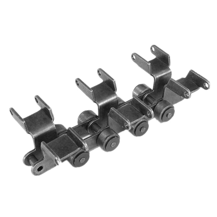
China Chain and sprocket factory : Transmission drive chain link repair in Baghdad Iraq Duplex Large Conveyor Steel Idler Metric Roller Chain Tensioner Drive Stainless Steel Aluminum Driven Gears and Industrial Sprocket with ce certificate top quality low price
We – EPG Group the greatest Chain and agricultural gearbox manufacturing unit in China with 5 distinct branches. For more particulars: Cell/whatsapp/telegram/Kakao us at: 0086-13083988828
In 2000, EPG took the guide in getting ISO14001 environment administration certificate and thereafter passed the inspection of thoroughly clean creation and recycling financial system, successful the title of “Zhejiang Eco-friendly Business”.help we have obtained the believe in of customers globally. a specialised provider of a complete selection of chains, sprockets, gears, equipment racks, V-belts, couplings and reducers, pto shaft, agricultural gearboxes….needed. Common one-strand roller chain, standardized by ASME, is an assembly of alternating pin hyperlinks and roller back links. The distance between pin centers is known as the pitch. The pitch is what categorizes the size of the chain. The more substantial the pitch, the larger the load score. Chains with tiny pitches carry scaled-down hundreds, operate much more quietly, and at larger speeds. Multi-strand, little-pitch roller chains are a great answer for higher-load, large-pace applications.
transmission duplex massive conveyor steel idler metric roller chain tensioner drive stainless steel aluminum driven gears and industrial sprocket
Manufacturer of Sprocket, Chain sprockets, wheel and sprocket, push sprocket, sprocket wheel, taper lock sprocket, equipment sprocket, idle sprocket, motorcycle sprocket and stainless steel sprocket, can interchange and change with martin size sprocket, jt size sprockets, did dimension chain sprocket and so on.
The use of unique products manufacturer’s (OEM) part numbers or trademarks , e.g. CASE® and John Deere® are for reference needs only and for indicating merchandise use and compatibility. Our business and the shown alternative components contained herein are not sponsored, accepted, or manufactured by the OEM.


Best China manufacturer & factory T in Tasikmalaya Indonesia Series 4 1 ratio 90 degree gearbox for agricultural t gearbox motor 3 phase gearbox aluminium hypoid gears With high quality best price

We will provide best services and high quality proThe company covering 88,000 square meters, has advanced equipment and strong technical strength, such as the numerical control machine tools and machining centers, CAD/CAM system, industrial robot etc. ducts with all sincerity. a specialized supplier of a full range of chains, sprockets, gears, gear racks, V-belts, couplings and reducers, pto shaft, agricultural gearboxes….
Overview
Quick Details
- Applicable Industries:
-
Building Material Shops
- Gearing Arrangement:
-
Bevel / Miter
- Output Torque:
-
Up to 3378Nm
- Input Speed:
-
750-1500rpm
- Output Speed:
-
3~1450r/min
- Place of Origin:Zhejiang, China
- Brand Name:
-
OEM
- Certification:
-
ISO9001-2008
- Mount Position:
-
Foot Mounted
- Bearing:
-
C&U
- gear precision grade:
-
din 4
Supply Ability
- Supply Ability:
- 1000 Unit/Units per Month
Packaging & Delivery
- Packaging Details
- Standard wooden case
- Port
- Ningbo Port, Shanghai Port
-
Lead Time
: -
Quantity(Boxes) 1 – 1 BUILDING ON LEADERSHIP IN INNOVATION Our investments in research and development significantly exceed the industry average. This is a result of our distinctive culture of innovation.
>1 Est. Time(days) 20 To be negotiated
Online Customization
PTO shaft connectors on tractors are not standardized which can lead to complications when connecting the PTO shaft. For example, some older tractor models have the connection flange closer to the tractor itself making it difficult to connect and lead to a potential safety hazard.
Product Description
T Series 4/1 ratio 90 degree gearbox for agricultural t gearbox motor 3 phase gearbox aluminium hypoid gears
Advantage:
-Self-locking ability
-Can be driven directly by motor or other power or manual
-Can be customized according user’s demand
-Compact configuration, small size, lightweight
-Convenient installation, flexible operation
-High reliability and stability
-Long service life
-More connection form etc.
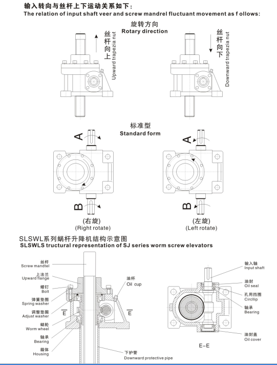
Screw jak is applied to all fields for lifting or pulling, such as Aircraft maintenance platform, Solar plate, machinery, metallurgy, water conservancy, medical treatment, chemical industry, culture and hygienist etc.
Specifications:
1.Tseries sprial bevel gear reducer with various types are standardized
2.all ratio of 1:1,1.5:1;2:1;2.5:1;3:1;4:1;and 5:1 are actual ones,
3.average efficiency is 98%.
|
Product Name |
T series Spiral Bevel Gearbox |
|
model no. |
T2, T4, T6, T7, T8, T10, T12, T16, T20, T25 |
|
Ratio |
1:1, 1.5:1, 2:1, 2.5:1,3:1,4:1,5:1 |
|
gear Material |
high grade synthetic diamond 50CrMnT |
|
Gear Processing |
Grinding finish by HOFLER Grinding Machines, Precision grade : DIN 4 |
|
spindle |
high purity steel alloy 40Cr piece |
|
Noise Test |
Bellow 65dB |
|
Warranty |
1 year |

Products Show

Related product
Company Profile
Packing & Delivery