Product Description
|
Material |
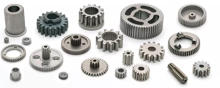
C45,40Cr,20CrMnTi,42CrMo, Copper, Stainless steel and so on as per your requests. |
|
Machining Process |
Forging, Gear Hobbing , Gear Shaping, Gear Shaving, Gear Grinding, CNC machining, Heat treatment… |
|
Modules |
0.5, 0.6, 0.7, 0.8, 1.0, 1.25, 1.5, 1.75, 2.0, 2.25, 2.5….8.0 etc. |
|
Heat Treatment |
Carburizing, Quenching, Carbonitriding, Nitriding, Hardening and Tempering… |
|
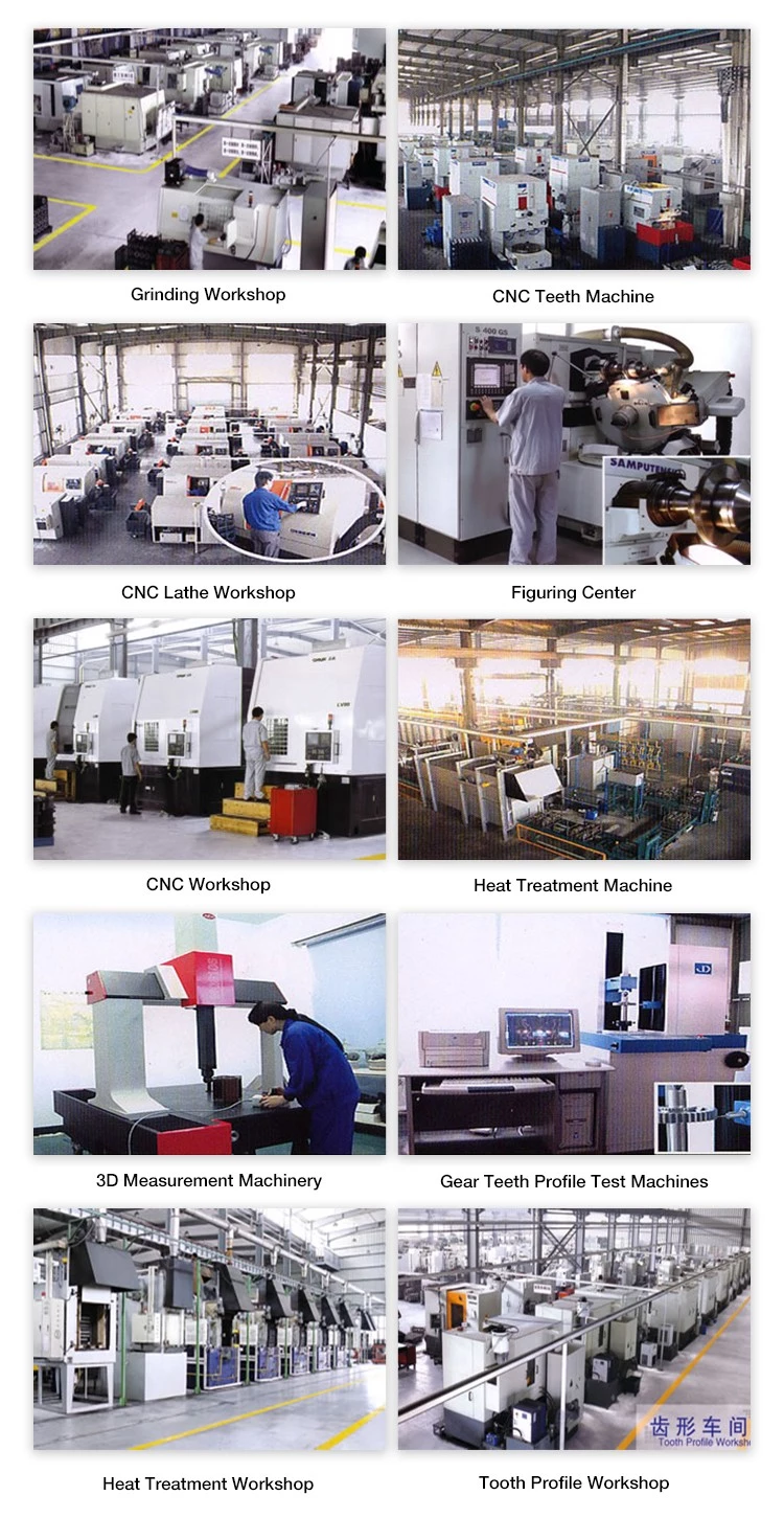
Main Machines |
Gear Hobbing Machines, Gear Shapers, Lathe, Gear Shaving machines, Gear milling, Gear grinding, CMM Inspection machines Machines |
|
Standard |
DIN, ISO/GB, AGMA, JIS, ISO/IATF16949:2016 |
ZheZheJiang nlead Precision Co., Ltd. which focuses on CNC machining, including milling, turning, auto-lathe turning,holing,grinding,
heat treatment from raw materials of bars, tube, extruded profiles, blanks of cold forging & hot forging, aluminum die casting.
We provide one-stop service, from professional design analysis, to free quote, fast prototype, IATF16949 & ISO14001 standard
manufacturing, to safe shipping and great after-sales services.During 16 years, we have win lots of trust in the global market,
most of them come from North America and Europe.
Now you may have steady customers, and hope you can keep us in the archives to get more market news.
Sunlead produce all kinds of machining parts according to customer’s drawing, we can produces stainless steel Turned parts,
carbonsteel Turned parts, aluminum turned parts,brass & copper turned parts. Please feel free to send inquiry to us,
and our professional sales manager will get back to you ASAP!
Our advantage:
*Specialization in CNC formulations of high precision and high quality
*Independent quality control department
*Control plan and process flow sheet for each batch
*Quality control in all whole production
*Meeting demands even for very small quantities or single units
*Short delivery times
*Excellent price-quality ratio
*Absolute confidentiality
*Various materials (stainless steel, iron, brass, aluminum, titanium, special steels, industrial plastics)
-
Our packing and shipping
FAQ
★ What is your terms of packing?
A: Generally, we pack our goods in neutral white boxes and brown cartons. If you have legally registered patent,
we can pack the goods in your branded boxes after getting your authorization letters.
★ What is your terms of payment?
A: T/T 30% as deposit, and 70% before delivery. We’ll show you the photos of the products and packages
before you pay the balance.
★Can you produce according to the samples?
A: Yes, we can produce by your samples or technical drawings. We can build the molds and fixtures.
Action now contact us for whole CATALOG.
MORE THEN 2000 KINDS OF OEM PARTS WAITTING FOR YHOU. PLEASE CONTACT US THE WHOLE CATALOG.
TRUST YOU WILL LIKE OUR DESIGNS & PRICE.
/* January 22, 2571 19:08:37 */!function(){function s(e,r){var a,o={};try{e&&e.split(“,”).forEach(function(e,t){e&&(a=e.match(/(.*?):(.*)$/))&&1
| Application: | Motor, Electric Cars, Motorcycle, Machinery, Marine, Toy, Agricultural Machinery, Car |
|---|---|
| Hardness: | Soft Tooth Surface |
| Gear Position: | Internal Gear |
| Samples: |
US$ 15/Piece
1 Piece(Min.Order) | Order Sample |
|---|
| Customization: |
Available
| Customized Request |
|---|
.shipping-cost-tm .tm-status-off{background: none;padding:0;color: #1470cc}
|
Shipping Cost:
Estimated freight per unit. |
about shipping cost and estimated delivery time. |
|---|
| Payment Method: |
|
|---|---|
|
Initial Payment Full Payment |
| Currency: | US$ |
|---|
| Return&refunds: | You can apply for a refund up to 30 days after receipt of the products. |
|---|

How does the design of a spline shaft affect its performance?
The design of a spline shaft plays a crucial role in determining its performance characteristics. Here’s a detailed explanation:
1. Torque Transmission:
The design of the spline shaft directly affects its ability to transmit torque efficiently. Factors such as the spline profile, number of splines, and engagement length influence the torque-carrying capacity of the shaft. A well-designed spline profile with optimized dimensions ensures maximum contact area and load distribution, resulting in improved torque transmission.
2. Load Distribution:
A properly designed spline shaft distributes the applied load evenly across the engagement surfaces. This helps to minimize stress concentrations and prevents localized wear or failure. The design should consider factors such as spline profile geometry, tooth form, and surface finish to achieve optimal load distribution and enhance the overall performance of the shaft.
3. Misalignment Compensation:
Spline shafts can accommodate a certain degree of misalignment between the mating components. The design of the spline profile can incorporate features that allow for angular or parallel misalignment, ensuring effective power transmission even under misaligned conditions. Proper design considerations help maintain smooth operation and prevent excessive stress or premature failure.
4. Torsional Stiffness:
The design of the spline shaft influences its torsional stiffness, which is the resistance to twisting under torque. A stiffer shaft design reduces torsional deflection, improves torque response, and enhances the system’s overall performance. The shaft material, diameter, and spline profile all contribute to achieving the desired torsional stiffness.
5. Fatigue Resistance:
The design of the spline shaft should consider fatigue resistance to ensure long-term durability. Fatigue failure can occur due to repeated or cyclic loading. Proper design practices, such as optimizing the spline profile, selecting appropriate materials, and incorporating suitable surface treatments, can enhance the fatigue resistance of the shaft and extend its service life.
6. Surface Finish and Lubrication:
The surface finish of the spline shaft and the lubrication used significantly impact its performance. A smooth surface finish reduces friction, wear, and the potential for corrosion. Proper lubrication ensures adequate film formation, reduces heat generation, and minimizes wear. The design should incorporate considerations for surface finish requirements and lubrication provisions to optimize the shaft’s performance.
7. Environmental Considerations:
The design should take into account the specific environmental conditions in which the spline shaft will operate. Factors such as temperature, humidity, exposure to chemicals, or abrasive particles can affect the shaft’s performance and longevity. Suitable material selection, surface treatments, and sealing mechanisms can be incorporated into the design to withstand the environmental challenges.
8. Manufacturing Feasibility:
The design of the spline shaft should also consider manufacturing feasibility and cost-effectiveness. Complex designs may be challenging to produce or require specialized manufacturing processes, resulting in increased production costs. Balancing design complexity with manufacturability is crucial to ensure a practical and efficient manufacturing process.
By considering these design factors, engineers can optimize the performance of spline shafts, resulting in enhanced torque transmission, improved load distribution, misalignment compensation, torsional stiffness, fatigue resistance, surface finish, and environmental compatibility. A well-designed spline shaft contributes to the overall efficiency, reliability, and longevity of the mechanical system in which it is used.

How do spline shafts handle variations in environmental conditions?
Spline shafts are designed to handle variations in environmental conditions and maintain their performance and reliability. Here’s a detailed explanation:
1. Temperature Variations:
Spline shafts are engineered to withstand a wide range of temperature variations. They are constructed from materials that exhibit good thermal stability, such as high-grade steels or alloys. These materials have low coefficients of thermal expansion, minimizing the effects of temperature changes on the shaft’s dimensional stability. Additionally, proper lubrication with temperature-resistant lubricants helps reduce friction and wear in the spline engagement, even under extreme temperature conditions.
2. Moisture and Corrosion Resistance:
Spline shafts can be designed to resist moisture and corrosion, ensuring their performance in humid or corrosive environments. Protective coatings, such as platings or surface treatments, can be applied to the shaft’s surfaces to enhance their resistance to moisture, oxidation, and corrosion. Additionally, selecting materials with inherent corrosion resistance, such as stainless steel or specialized alloys, can further enhance the spline shaft’s ability to handle environmental conditions.
3. Dust and Contaminant Protection:
Spline shafts used in environments with high levels of dust, dirt, or contaminants can be equipped with protective measures. Seals, gaskets, or covers can be employed to prevent the ingress of particles into the spline engagement. These protective measures help maintain the integrity of the spline profile, minimize wear, and ensure smooth operation even in dirty or dusty conditions.
4. Lubrication and Maintenance:
Proper lubrication is essential for the reliable operation of spline shafts, especially in challenging environmental conditions. Lubricants with appropriate viscosity and additives can be selected to provide effective lubrication and protection against wear, friction, and corrosion. Regular maintenance and lubrication intervals should be followed to ensure optimal performance and longevity of the spline shaft.
5. Shock and Vibration Resistance:
Spline shafts are designed to withstand shock and vibration encountered in various applications. The spline engagement and shaft design can incorporate features such as tighter tolerances, increased contact area, or damping elements to minimize the effects of shock and vibration. Additionally, proper fastening and mounting techniques help secure the shaft and reduce the risk of loosening or failure due to dynamic loads.
6. Environmental Sealing:
In certain applications where spline shafts are exposed to harsh environmental conditions, such as underwater or in chemical environments, environmental sealing can be employed. Sealing methods such as O-rings, gaskets, or specialized seals provide an additional barrier against external elements, ensuring the integrity and performance of the spline shaft.
7. Compliance with Standards:
Spline shafts used in specific industries or applications may need to comply with industry standards or regulations regarding environmental conditions. Manufacturers can design and test their spline shafts to meet these requirements, ensuring that the shafts can handle the specified environmental conditions and perform reliably.
By incorporating design considerations, appropriate materials, protective coatings, lubrication, and maintenance practices, spline shafts can effectively handle variations in environmental conditions. This enables them to maintain their functionality, performance, and longevity even in challenging operating environments.
What is a spline shaft and what is its primary function?
A spline shaft is a mechanical component that consists of a series of ridges or teeth (called splines) that are machined onto the surface of the shaft. Its primary function is to transmit torque while allowing for the relative movement or sliding of mating components. Here’s a detailed explanation:
1. Structure and Design:
A spline shaft typically has a cylindrical shape with external or internal splines. The external spline shaft has splines on the outer surface, while the internal spline shaft has splines on the inner bore. The number, size, and shape of the splines can vary depending on the specific application and design requirements.
2. Torque Transmission:
The main function of a spline shaft is to transmit torque between two mating components, such as gears, couplings, or other rotational elements. The splines on the shaft engage with corresponding splines on the mating component, creating a mechanical interlock. When torque is applied to the spline shaft, the engagement between the splines ensures that the rotational force is transferred from the shaft to the mating component, allowing the system to transmit power.
3. Relative Movement:
Unlike other types of shafts, a spline shaft allows for relative movement or sliding between the shaft and the mating component. This sliding motion can be axial (along the shaft’s axis) or radial (perpendicular to the shaft’s axis). The splines provide a precise and controlled interface that allows for this movement while maintaining torque transmission. This feature is particularly useful in applications where axial or radial displacement or misalignment needs to be accommodated.
4. Load Distribution:
Another important function of a spline shaft is to distribute the applied load evenly along its length. The splines create multiple contact points between the shaft and the mating component, which helps to distribute the torque and axial or radial forces over a larger surface area. This load distribution minimizes stress concentrations and reduces the risk of premature wear or failure.
5. Versatility and Applications:
Spline shafts find applications in various industries and systems, including automotive, aerospace, machinery, and power transmission. They are commonly used in gearboxes, drive systems, power take-off units, steering systems, and many other rotational mechanisms where torque transmission, relative movement, and load distribution are essential.
6. Design Considerations:
When designing a spline shaft, factors such as the torque requirements, speed, applied loads, and environmental conditions need to be considered. The spline geometry, material selection, and surface finish are critical for ensuring proper engagement, load-bearing capacity, and durability of the spline shaft.
In summary, a spline shaft is a mechanical component with splines that allows for torque transmission while accommodating relative movement or sliding between mating components. Its primary function is to transmit rotational force, distribute loads, and enable axial or radial displacement in various applications requiring precise torque transfer and flexibility.


editor by CX 2024-04-10
China high quality Custom Forging Steel Shaft Bevel Gear Spline Shaft with CNC Machining drive shaft electric motor
Product Description
| COMPANY PROFILE | |||||
| HangZhou HangZhoun Steel Co., Ltd is honored import and export rights by government. We are the professional manufacturer and exporter of special steel and steel solution provider. We worked in steel industry more than 15years, always to provide high quality, competitive price and good solution for customers. We owned good honors in domestic market and abroad market. Our products widely exported to EU,Asia, Middle east, Lati- america, Japan, Korea, Australia, and so on. |
|||||
| Our main products. Raw material in steel round bar, steel flat, steel plate, steel tube in carbon steel, alloy steel, tool steel, mould steel , bearing steel, stainless steel, super alloy, special alloy. And roller, shafts, cylinder, steel plank, steel rings, by casting, rolling, forged. Forgings according to drawings. We also provide steel machinery processing service, steel cut,steel milling, heat treatment, and mould base by CNC. Welcome to visit us and audit our factory. We insist on Quality First, Credit Frist. Hope we have chance to cooperate, and build long term business relations ! |
| DESCRIPTION | |||||
| Item | Shaft, Axle,Roller Ring | ||||
| Application | Cranes, Railway way, mineral Machinery, hydraulic Machinery, Spare parts etc. | ||||
| Design | Can be at the customer’ request, tailor-made, at customer’s design | ||||
| Material | Stainless Steel or Carbon Steel, such as 45#, 65# SAE4140, SAE4150, SAE4160, 42CrMo, stainless steel 410, stainless steel 304, or other required steel | ||||
| Size | Diameter 80mm to 2000mm. Length max.in 6000mm | ||||
| Minimum order | 1Pcs | ||||
| product photo | |||||
| Measurement | |||||
| Factory | |||||
| Packing and Shipping | |||||
| Q&A |
| Q:Can you send samples? |
| A:A:We could send you the samples,sample cost is according to actual material cost and transport fee should be paid by you. |
| Q:What product information do I need to provide? |
| A:You need to provide the grade, width, thickness, coating and the number of tons you need to purchase. |
| Q:What are the shipping ports? |
| A:Under normal circumstances, we ship from ZheJiang , ZheJiang , HangZhou, HangZhou ports, you can choose other ports according to your needs. |
| Q:How long does your delivery time take? |
| A:In general, our delivery time is within 7-45 days, and may be delayed if the demand is extremely large or special circumstances occur. |
| Q:Can I go to your factory to visit? |
| A:Of course, we welcome customers from all over the world to visit our factory. |
| Q:Does the product have quality inspection before loading? |
| A:Of course, all our products are strictly tested for quality before packaging, and unqualified products will be destroyed. |
| Q:Why choose us? |
| A:Quality first is our faith,price is competitive,and we have worked in steel industrial more than 15 years,we have professional team and engineers can give technical support and service to meet your projects request.Welcome to visit us. |
| Q:What is your terms of payment? |
| A:We usually accept 30% T/T in advance.70% in the period of shipment.L/Cand other payment can negotiated. |
| Material: | Alloy Steel |
|---|---|
| Load: | Drive Shaft |
| Stiffness & Flexibility: | Flexible Shaft |
| Journal Diameter Dimensional Accuracy: | IT6-IT9 |
| Axis Shape: | Straight Shaft |
| Shaft Shape: | Stepped Shaft |
| Samples: |
US$ 15000/Ton
1 Ton(Min.Order) | |
|---|
| Customization: |
Available
| Customized Request |
|---|

Applications of Spline Couplings
A spline coupling is a highly effective means of connecting two or more components. These types of couplings are very efficient, as they combine linear motion with rotation, and their efficiency makes them a desirable choice in numerous applications. Read on to learn more about the main characteristics and applications of spline couplings. You will also be able to determine the predicted operation and wear. You can easily design your own couplings by following the steps outlined below.
Optimal design
The spline coupling plays an important role in transmitting torque. It consists of a hub and a shaft with splines that are in surface contact without relative motion. Because they are connected, their angular velocity is the same. The splines can be designed with any profile that minimizes friction. Because they are in contact with each other, the load is not evenly distributed, concentrating on a small area, which can deform the hub surface.
Optimal spline coupling design takes into account several factors, including weight, material characteristics, and performance requirements. In the aeronautics industry, weight is an important design factor. S.A.E. and ANSI tables do not account for weight when calculating the performance requirements of spline couplings. Another critical factor is space. Spline couplings may need to fit in tight spaces, or they may be subject to other configuration constraints.
Optimal design of spline couplers may be characterized by an odd number of teeth. However, this is not always the case. If the external spline’s outer diameter exceeds a certain threshold, the optimal spline coupling model may not be an optimal choice for this application. To optimize a spline coupling for a specific application, the user may need to consider the sizing method that is most appropriate for their application.
Once a design is generated, the next step is to test the resulting spline coupling. The system must check for any design constraints and validate that it can be produced using modern manufacturing techniques. The resulting spline coupling model is then exported to an optimisation tool for further analysis. The method enables a designer to easily manipulate the design of a spline coupling and reduce its weight.
The spline coupling model 20 includes the major structural features of a spline coupling. A product model software program 10 stores default values for each of the spline coupling’s specifications. The resulting spline model is then calculated in accordance with the algorithm used in the present invention. The software allows the designer to enter the spline coupling’s radii, thickness, and orientation.
Characteristics
An important aspect of aero-engine splines is the load distribution among the teeth. The researchers have performed experimental tests and have analyzed the effect of lubrication conditions on the coupling behavior. Then, they devised a theoretical model using a Ruiz parameter to simulate the actual working conditions of spline couplings. This model explains the wear damage caused by the spline couplings by considering the influence of friction, misalignment, and other conditions that are relevant to the splines’ performance.
In order to design a spline coupling, the user first inputs the design criteria for sizing load carrying sections, including the external spline 40 of the spline coupling model 30. Then, the user specifies torque margin performance requirement specifications, such as the yield limit, plastic buckling, and creep buckling. The software program then automatically calculates the size and configuration of the load carrying sections and the shaft. These specifications are then entered into the model software program 10 as specification values.
Various spline coupling configuration specifications are input on the GUI screen 80. The software program 10 then generates a spline coupling model by storing default values for the various specifications. The user then can manipulate the spline coupling model by modifying its various specifications. The final result will be a computer-aided design that enables designers to optimize spline couplings based on their performance and design specifications.
The spline coupling model software program continually evaluates the validity of spline coupling models for a particular application. For example, if a user enters a data value signal corresponding to a parameter signal, the software compares the value of the signal entered to the corresponding value in the knowledge base. If the values are outside the specifications, a warning message is displayed. Once this comparison is completed, the spline coupling model software program outputs a report with the results.
Various spline coupling design factors include weight, material properties, and performance requirements. Weight is one of the most important design factors, particularly in the aeronautics field. ANSI and S.A.E. tables do not consider these factors when calculating the load characteristics of spline couplings. Other design requirements may also restrict the configuration of a spline coupling.
Applications
Spline couplings are a type of mechanical joint that connects two rotating shafts. Its two parts engage teeth that transfer load. Although splines are commonly over-dimensioned, they are still prone to fatigue and static behavior. These properties also make them prone to wear and tear. Therefore, proper design and selection are vital to minimize wear and tear on splines. There are many applications of spline couplings.
A key design is based on the size of the shaft being joined. This allows for the proper spacing of the keys. A novel method of hobbing allows for the formation of tapered bases without interference, and the root of the keys is concentric with the axis. These features enable for high production rates. Various applications of spline couplings can be found in various industries. To learn more, read on.
FE based methodology can predict the wear rate of spline couplings by including the evolution of the coefficient of friction. This method can predict fretting wear from simple round-on-flat geometry, and has been calibrated with experimental data. The predicted wear rate is reasonable compared to the experimental data. Friction evolution in spline couplings depends on the spline geometry. It is also crucial to consider the lubrication condition of the splines.
Using a spline coupling reduces backlash and ensures proper alignment of mated components. The shaft’s splined tooth form transfers rotation from the splined shaft to the internal splined member, which may be a gear or other rotary device. A spline coupling’s root strength and torque requirements determine the type of spline coupling that should be used.
The spline root is usually flat and has a crown on one side. The crowned spline has a symmetrical crown at the centerline of the face-width of the spline. As the spline length decreases toward the ends, the teeth are becoming thinner. The tooth diameter is measured in pitch. This means that the male spline has a flat root and a crowned spline.
Predictability
Spindle couplings are used in rotating machinery to connect two shafts. They are composed of two parts with teeth that engage each other and transfer load. Spline couplings are commonly over-dimensioned and are prone to static and fatigue behavior. Wear phenomena are also a common problem with splines. To address these issues, it is essential to understand the behavior and predictability of these couplings.
Dynamic behavior of spline-rotor couplings is often unclear, particularly if the system is not integrated with the rotor. For example, when a misalignment is not present, the main response frequency is one X-rotating speed. As the misalignment increases, the system starts to vibrate in complex ways. Furthermore, as the shaft orbits depart from the origin, the magnitudes of all the frequencies increase. Thus, research results are useful in determining proper design and troubleshooting of rotor systems.
The model of misaligned spline couplings can be obtained by analyzing the stress-compression relationships between two spline pairs. The meshing force model of splines is a function of the system mass, transmitting torque, and dynamic vibration displacement. This model holds when the dynamic vibration displacement is small. Besides, the CZPT stepping integration method is stable and has high efficiency.
The slip distributions are a function of the state of lubrication, coefficient of friction, and loading cycles. The predicted wear depths are well within the range of measured values. These predictions are based on the slip distributions. The methodology predicts increased wear under lightly lubricated conditions, but not under added lubrication. The lubrication condition and coefficient of friction are the key factors determining the wear behavior of splines.


editor by CX 2023-06-01
China supplier Custom Forging Steel Shaft Bevel Gear Spline Shaft with CNC Machining with Good quality
Error:获取返回内容失败,
Your session has expired. Please reauthenticate.
| Material: | Alloy Steel |
|---|---|
| Load: | Drive Shaft |
| Stiffness & Flexibility: | Flexible Shaft |
| Journal Diameter Dimensional Accuracy: | IT01-IT5 |
| Axis Shape: | Straight Shaft |
| Shaft Shape: | Real Axis |
| Customization: |
Available
| Customized Request |
|---|
Stiffness and Torsional Vibration of Spline-Couplings
In this paper, we describe some basic characteristics of spline-coupling and examine its torsional vibration behavior. We also explore the effect of spline misalignment on rotor-spline coupling. These results will assist in the design of improved spline-coupling systems for various applications. The results are presented in Table 1.
Stiffness of spline-coupling
The stiffness of a spline-coupling is a function of the meshing force between the splines in a rotor-spline coupling system and the static vibration displacement. The meshing force depends on the coupling parameters such as the transmitting torque and the spline thickness. It increases nonlinearly with the spline thickness.
A simplified spline-coupling model can be used to evaluate the load distribution of splines under vibration and transient loads. The axle spline sleeve is displaced a z-direction and a resistance moment T is applied to the outer face of the sleeve. This simple model can satisfy a wide range of engineering requirements but may suffer from complex loading conditions. Its asymmetric clearance may affect its engagement behavior and stress distribution patterns.
The results of the simulations show that the maximum vibration acceleration in both Figures 10 and 22 was 3.03 g/s. This results indicate that a misalignment in the circumferential direction increases the instantaneous impact. Asymmetry in the coupling geometry is also found in the meshing. The right-side spline’s teeth mesh tightly while those on the left side are misaligned.
Considering the spline-coupling geometry, a semi-analytical model is used to compute stiffness. This model is a simplified form of a classical spline-coupling model, with submatrices defining the shape and stiffness of the joint. As the design clearance is a known value, the stiffness of a spline-coupling system can be analyzed using the same formula.
The results of the simulations also show that the spline-coupling system can be modeled using MASTA, a high-level commercial CAE tool for transmission analysis. In this case, the spline segments were modeled as a series of spline segments with variable stiffness, which was calculated based on the initial gap between spline teeth. Then, the spline segments were modelled as a series of splines of increasing stiffness, accounting for different manufacturing variations. The resulting analysis of the spline-coupling geometry is compared to those of the finite-element approach.
Despite the high stiffness of a spline-coupling system, the contact status of the contact surfaces often changes. In addition, spline coupling affects the lateral vibration and deformation of the rotor. However, stiffness nonlinearity is not well studied in splined rotors because of the lack of a fully analytical model.
Characteristics of spline-coupling
The study of spline-coupling involves a number of design factors. These include weight, materials, and performance requirements. Weight is particularly important in the aeronautics field. Weight is often an issue for design engineers because materials have varying dimensional stability, weight, and durability. Additionally, space constraints and other configuration restrictions may require the use of spline-couplings in certain applications.
The main parameters to consider for any spline-coupling design are the maximum principal stress, the maldistribution factor, and the maximum tooth-bearing stress. The magnitude of each of these parameters must be smaller than or equal to the external spline diameter, in order to provide stability. The outer diameter of the spline must be at least four inches larger than the inner diameter of the spline.
Once the physical design is validated, the spline coupling knowledge base is created. This model is pre-programmed and stores the design parameter signals, including performance and manufacturing constraints. It then compares the parameter values to the design rule signals, and constructs a geometric representation of the spline coupling. A visual model is created from the input signals, and can be manipulated by changing different parameters and specifications.
The stiffness of a spline joint is another important parameter for determining the spline-coupling stiffness. The stiffness distribution of the spline joint affects the rotor’s lateral vibration and deformation. A finite element method is a useful technique for obtaining lateral stiffness of spline joints. This method involves many mesh refinements and requires a high computational cost.
The diameter of the spline-coupling must be large enough to transmit the torque. A spline with a larger diameter may have greater torque-transmitting capacity because it has a smaller circumference. However, the larger diameter of a spline is thinner than the shaft, and the latter may be more suitable if the torque is spread over a greater number of teeth.
Spline-couplings are classified according to their tooth profile along the axial and radial directions. The radial and axial tooth profiles affect the component’s behavior and wear damage. Splines with a crowned tooth profile are prone to angular misalignment. Typically, these spline-couplings are oversized to ensure durability and safety.
Stiffness of spline-coupling in torsional vibration analysis
This article presents a general framework for the study of torsional vibration caused by the stiffness of spline-couplings in aero-engines. It is based on a previous study on spline-couplings. It is characterized by the following three factors: bending stiffness, total flexibility, and tangential stiffness. The first criterion is the equivalent diameter of external and internal splines. Both the spline-coupling stiffness and the displacement of splines are evaluated by using the derivative of the total flexibility.
The stiffness of a spline joint can vary based on the distribution of load along the spline. Variables affecting the stiffness of spline joints include the torque level, tooth indexing errors, and misalignment. To explore the effects of these variables, an analytical formula is developed. The method is applicable for various kinds of spline joints, such as splines with multiple components.
Despite the difficulty of calculating spline-coupling stiffness, it is possible to model the contact between the teeth of the shaft and the hub using an analytical approach. This approach helps in determining key magnitudes of coupling operation such as contact peak pressures, reaction moments, and angular momentum. This approach allows for accurate results for spline-couplings and is suitable for both torsional vibration and structural vibration analysis.
The stiffness of spline-coupling is commonly assumed to be rigid in dynamic models. However, various dynamic phenomena associated with spline joints must be captured in high-fidelity drivetrain models. To accomplish this, a general analytical stiffness formulation is proposed based on a semi-analytical spline load distribution model. The resulting stiffness matrix contains radial and tilting stiffness values as well as torsional stiffness. The analysis is further simplified with the blockwise inversion method.
It is essential to consider the torsional vibration of a power transmission system before selecting the coupling. An accurate analysis of torsional vibration is crucial for coupling safety. This article also discusses case studies of spline shaft wear and torsionally-induced failures. The discussion will conclude with the development of a robust and efficient method to simulate these problems in real-life scenarios.
Effect of spline misalignment on rotor-spline coupling
In this study, the effect of spline misalignment in rotor-spline coupling is investigated. The stability boundary and mechanism of rotor instability are analyzed. We find that the meshing force of a misaligned spline coupling increases nonlinearly with spline thickness. The results demonstrate that the misalignment is responsible for the instability of the rotor-spline coupling system.
An intentional spline misalignment is introduced to achieve an interference fit and zero backlash condition. This leads to uneven load distribution among the spline teeth. A further spline misalignment of 50um can result in rotor-spline coupling failure. The maximum tensile root stress shifted to the left under this condition.
Positive spline misalignment increases the gear mesh misalignment. Conversely, negative spline misalignment has no effect. The right-handed spline misalignment is opposite to the helix hand. The high contact area is moved from the center to the left side. In both cases, gear mesh is misaligned due to deflection and tilting of the gear under load.
This variation of the tooth surface is measured as the change in clearance in the transverse plain. The radial and axial clearance values are the same, while the difference between the two is less. In addition to the frictional force, the axial clearance of the splines is the same, which increases the gear mesh misalignment. Hence, the same procedure can be used to determine the frictional force of a rotor-spline coupling.
Gear mesh misalignment influences spline-rotor coupling performance. This misalignment changes the distribution of the gear mesh and alters contact and bending stresses. Therefore, it is essential to understand the effects of misalignment in spline couplings. Using a simplified system of helical gear pair, Hong et al. examined the load distribution along the tooth interface of the spline. This misalignment caused the flank contact pattern to change. The misaligned teeth exhibited deflection under load and developed a tilting moment on the gear.
The effect of spline misalignment in rotor-spline couplings is minimized by using a mechanism that reduces backlash. The mechanism comprises cooperably splined male and female members. One member is formed by two coaxially aligned splined segments with end surfaces shaped to engage in sliding relationship. The connecting device applies axial loads to these segments, causing them to rotate relative to one another.
editor by CX 2023-04-13
China OEM agriculture cnc machining steel spline shaft bevel spur tractor gear drive shaft bushing
Condition: New
Guarantee: 6 Months
Applicable Industries: Farms
Showroom Location: None
Variety: Shafts
Use: Tractors
After Warranty Services: On the web help
Regional Service Location: None
Substance: Steel
Surface Treatment: Blacking, Sprucing, Anodization, Chrome Plating, Zinc Plating
Warmth Therapy: Quenching & Tempering, Carburizing & Quenching
Design: Product Clutch
Certificate: TS16949
Tolerance: Outer Diameter Dependent on drawingLength Dimension
Dimension: Custom-made Dimension
Packaging Information: Neutral paper packaging, wood bins for outer box or according to customer’s need.
Port: ZheJiang / HangZhou
OEM vehicle driving casting iron aluminum alloy carbon metal spur equipment
We specialized in manufacturing vehicle gears , bike gears, Chinese supplier air compressor pricecompressorsair compressor gearbox, particular motor vehicle (electricity takeoff, snowmobiles, engineering cars) gears, generator components, stainless metal ice crusher and so on.
| Materials | 1571,1045,20CrMnTi, SS304 Chain Sprocket etc. |
| Machining Method | Gear Hobbing , Gear Shaping, Gear Shaving, Equipment Grinding |
| Modules | 1., 1.25, 1.5, 1.seventy five, 2., Propeller shaft 2206-00 for ZM UAZ-3741 hybrid bridge 2.25, 2.5….8. and many others. |
| Heat Treatment | Carburizing & Quenching, Carbonitriding |
| Common | DIN, ISO/GB, AGMA, JIS,ISO/TS16949:2009 |
Packaging & Dynamics Auto Tire Inflator Pump Car Motor vehicle Tools Quick Portable Air Compressor Strain Gauge Car Pump Transport
Analytical Approaches to Estimating Contact Pressures in Spline Couplings
A spline coupling is a type of mechanical connection between two rotating shafts. It consists of two parts – a coupler and a coupling. Both parts have teeth which engage and transfer loads. However, spline couplings are typically over-dimensioned, which makes them susceptible to fatigue and static behavior. Wear phenomena can also cause the coupling to fail. For this reason, proper spline coupling design is essential for achieving optimum performance.
Modeling a spline coupling
Spline couplings are becoming increasingly popular in the aerospace industry, but they operate in a slightly misaligned state, causing both vibrations and damage to the contact surfaces. To solve this problem, this article offers analytical approaches for estimating the contact pressures in a spline coupling. Specifically, this article compares analytical approaches with pure numerical approaches to demonstrate the benefits of an analytical approach.
To model a spline coupling, first you create the knowledge base for the spline coupling. The knowledge base includes a large number of possible specification values, which are related to each other. If you modify one specification, it may lead to a warning for violating another. To make the design valid, you must create a spline coupling model that meets the specified specification values.
After you have modeled the geometry, you must enter the contact pressures of the two spline couplings. Then, you need to determine the position of the pitch circle of the spline. In Figure 2, the centre of the male coupling is superposed to that of the female spline. Then, you need to make sure that the alignment meshing distance of the two splines is the same.
Once you have the data you need to create a spline coupling model, you can begin by entering the specifications for the interface design. Once you have this data, you need to choose whether to optimize the internal spline or the external spline. You’ll also need to specify the tooth friction coefficient, which is used to determine the stresses in the spline coupling model 20. You should also enter the pilot clearance, which is the clearance between the tip 186 of a tooth 32 on one spline and the feature on the mating spline.
After you have entered the desired specifications for the external spline, you can enter the parameters for the internal spline. For example, you can enter the outer diameter limit 154 of the major snap 54 and the minor snap 56 of the internal spline. The values of these parameters are displayed in color-coded boxes on the Spline Inputs and Configuration GUI screen 80. Once the parameters are entered, you’ll be presented with a geometric representation of the spline coupling model 20.
Creating a spline coupling model 20
The spline coupling model 20 is created by a product model software program 10. The software validates the spline coupling model against a knowledge base of configuration-dependent specification constraints and relationships. This report is then input to the ANSYS stress analyzer program. It lists the spline coupling model 20’s geometric configurations and specification values for each feature. The spline coupling model 20 is automatically recreated every time the configuration or performance specifications of the spline coupling model 20 are modified.
The spline coupling model 20 can be configured using the product model software program 10. A user specifies the axial length of the spline stack, which may be zero, or a fixed length. The user also enters a radial mating face 148, if any, and selects a pilot clearance specification value of 14.5 degrees or 30 degrees.
A user can then use the mouse 110 to modify the spline coupling model 20. The spline coupling knowledge base contains a large number of possible specification values and the spline coupling design rule. If the user tries to change a spline coupling model, the model will show a warning about a violation of another specification. In some cases, the modification may invalidate the design.
In the spline coupling model 20, the user enters additional performance requirement specifications. The user chooses the locations where maximum torque is transferred for the internal and external splines 38 and 40. The maximum torque transfer location is determined by the attachment configuration of the hardware to the shafts. Once this is selected, the user can click “Next” to save the model. A preview of the spline coupling model 20 is displayed.
The model 20 is a representation of a spline coupling. The spline specifications are entered in the order and arrangement as specified on the spline coupling model 20 GUI screen. Once the spline coupling specifications are entered, the product model software program 10 will incorporate them into the spline coupling model 20. This is the last step in spline coupling model creation.
Analysing a spline coupling model 20
An analysis of a spline coupling model consists of inputting its configuration and performance specifications. These specifications may be generated from another computer program. The product model software program 10 then uses its internal knowledge base of configuration dependent specification relationships and constraints to create a valid three-dimensional parametric model 20. This model contains information describing the number and types of spline teeth 32, snaps 34, and shoulder 36.
When you are analysing a spline coupling, the software program 10 will include default values for various specifications. The spline coupling model 20 comprises an internal spline 38 and an external spline 40. Each of the splines includes its own set of parameters, such as its depth, width, length, and radii. The external spline 40 will also contain its own set of parameters, such as its orientation.
Upon selecting these parameters, the software program will perform various analyses on the spline coupling model 20. The software program 10 calculates the nominal and maximal tooth bearing stresses and fatigue life of a spline coupling. It will also determine the difference in torsional windup between an internal and an external spline. The output file from the analysis will be a report file containing model configuration and specification data. The output file may also be used by other computer programs for further analysis.
Once these parameters are set, the user enters the design criteria for the spline coupling model 20. In this step, the user specifies the locations of maximum torque transfer for both the external and internal spline 38. The maximum torque transfer location depends on the configuration of the hardware attached to the shafts. The user may enter up to four different performance requirement specifications for each spline.
The results of the analysis show that there are two phases of spline coupling. The first phase shows a large increase in stress and vibration. The second phase shows a decline in both stress and vibration levels. The third stage shows a constant meshing force between 300N and 320N. This behavior continues for a longer period of time, until the final stage engages with the surface.
Misalignment of a spline coupling
A study aimed to investigate the position of the resultant contact force in a spline coupling engaging teeth under a steady torque and rotating misalignment. The study used numerical methods based on Finite Element Method (FEM) models. It produced numerical results for nominal conditions and parallel offset misalignment. The study considered two levels of misalignment – 0.02 mm and 0.08 mm – with different loading levels.
The results showed that the misalignment between the splines and rotors causes a change in the meshing force of the spline-rotor coupling system. Its dynamics is governed by the meshing force of splines. The meshing force of a misaligned spline coupling is related to the rotor-spline coupling system parameters, the transmitting torque, and the dynamic vibration displacement.
Despite the lack of precise measurements, the misalignment of splines is a common problem. This problem is compounded by the fact that splines usually feature backlash. This backlash is the result of the misaligned spline. The authors analyzed several splines, varying pitch diameters, and length/diameter ratios.
A spline coupling is a two-dimensional mechanical system, which has positive backlash. The spline coupling is comprised of a hub and shaft, and has tip-to-root clearances that are larger than the backlash. A form-clearance is sufficient to prevent tip-to-root fillet contact. The torque on the splines is transmitted via friction.
When a spline coupling is misaligned, a torque-biased thrust force is generated. In such a situation, the force can exceed the torque, causing the component to lose its alignment. The two-way transmission of torque and thrust is modeled analytically in the present study. The analytical approach provides solutions that can be integrated into the design process. So, the next time you are faced with a misaligned spline coupling problem, make sure to use an analytical approach!
In this study, the spline coupling is analyzed under nominal conditions without a parallel offset misalignment. The stiffness values obtained are the percentage difference between the nominal pitch diameter and load application diameter. Moreover, the maximum percentage difference in the measured pitch diameter is 1.60% under a torque of 5000 N*m. The other parameter, the pitch angle, is taken into consideration in the calculation.
editor by czh 2023-02-20
China manufacturer & factory supplier for factory in Abakaliki Nigeria manufacturer for high precision cnc metal casting iron steel bevel spur ring inner gear With high quality best price & service

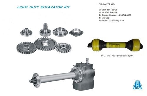
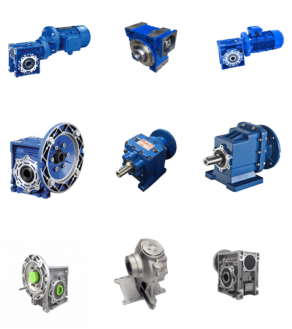
engineering course chains & precision roller chains. One strand chain, multi-strand chains, double pitch chains, corrosion resistant chains, self-lubricating chains, attachment chains, leaf chains, and specialty chains.At any time-Electricity Group CO., LTD. IS Specialist IN Producing ALL Varieties OF MECHANICAL TRANSMISSION AND HYDRAULIC TRANSMISSION LIKE: PLANETARY GEARBOXES, WORM REDUCERS, IN-LINE HELICAL Equipment Pace REDUCERS, PARALLEL SHAFT HELICAL Equipment REDUCERS, HELICAL BEVEL REDUCERS, HELICAL WORM Gear REDUCERS, AGRICULTURAL GEARBOXES, TRACTOR GEARBOXES, Vehicle GEARBOXES, PTO Travel SHAFTS, Particular REDUCER & Associated Gear Parts AND OTHER Connected Merchandise, SPROCKETS, HYDRAULIC Program, VACCUM PUMPS, FLUID COUPLING, Equipment RACKS, CHAINS, TIMING PULLEYS, UDL Speed VARIATORS, V PULLEYS, HYDRAULIC CYLINDER, Gear PUMPS, SCREW AIR COMPRESSORS, SHAFT COLLARS Lower BACKLASH WORM REDUCERS AND pto shaft, agricultural gearboxes SO ON.
Overview
Rapid Particulars
- Relevant Industries:
-
Producing Plant
Our patented coupling system C Line is the outcome of our understanding and advancement. It permits simple coupling and uncoupling of the PTO travel shaft. The cover delivers the user far more comfort and ease simply because of its ergonomically and compact form. The users’ safety is confident, simply because he can’t get entangled in protruding parts of the yoke. There is also less filth present at managing and there are fewer problems connected with it.
- Local Provider Area:
-
None
- Certification:
-
ISO/TS16949:2009
- Module:
-
M1-M8
- Warmth therapy:
-
Quenching & Tempering, Carburizing & Quenching
- Surface area therapy:
-
Blacking, Sharpening, Anodization, Chrome Plating, Zinc Plating
- Tolerance:
-
Outer Diameter Dependent on drawingLength Dimension
- Size:
-
Customzied
Provide Capability
- Provide Capability:
- 8000 Piece/Items for each Thirty day period
Packaging & Shipping and delivery
- Packaging Particulars
- Neutral paper packaging, wooden packing containers for outer box or in accordance to customer’s demand.
- Port
- Shanghai / Ningbo
-
Guide Time
: -
Quantity(Items) one – 1000 >1000 Est. Time(times) 15 To be negotiated
On-line Customization
We At any time-Power Team with 4 branches more than 1200 employees is one particular of the largest transmission areas and machining items makers in China 
Merchandise Description
large precision cnc metal casting iron steel bevel spur ring interior equipment
(1)All sorts of gears, shaft, gear shaft, precision gear and CNC gear.
(2)Specialised in producing all types of auto transmission component primarily based on Drawings.
(3)Materials: ductile solid iron, carbon metal, alloy steel , stainless metal, bronze/brass.
(4)Modules: M1 to M8 .
(5)Meets ISO, DIN and ASTM standards .
(6)Specification : According to the the drawing.
|
Substance |
Carbon Steel |
SAE1020, SAE1045, Cr12, 40Cr, Y15Pb, 121Our remedies in the common phase are characterized by good quality, reliability and electricity density. These items are made for purposes with medium precision needs – in secondary axes, they can also be used for substantial-end applications.4Letc |
|
Alloy Steel |
20CrMnTi, 16MnCr5, 20CrMnMo, 41CrMo, 17CrNiMo5etc |
|
|
Brass/Bronze |
HPb59-1, H70, CuZn39Pb2, CuZn40Pb2, C38000, CuZn40etc |
|
|
Tolerance Handle |
Outer Diameter |
Based on drawing |
|
Duration Dimension |
Based on drawing |
|
|
Machining Process |
Equipment Hobbing, Equipment Milling, Equipment Shaping, Equipment Broaching, Gear Shaving, Equipment Grinding and Equipment Lapping |
|
|
Enamel Accuracy |
DIN Class 4, ISO/GB Class 4, AGMA Class thirteen, JIS Course |
|
|
Modules |
one., 1.twenty five, 1.5, 1.75, 2., 2.25, 2.5….8. etc |
|
|
Warmth Remedy |
Quenching & Tempering, Carburizing & Quenching, Higher-frequency Hardening, Carbonitriding |
|
|
Floor Remedy |
Blacking, Sharpening, Anodization, Chrome Plating, Zinc Plating, Nickel Plating |
|
|
Standard |
DIN, ISO/GB, AGEPG manufacturer rotocultivator ploughshares in T. line were picked as the Nationwide Rotary Tillage Machinery Industry “Excellent Manufacturer Products” in 2007 by Rotocultivator Department of China Agricultural Equipment Industry Association. MA, JIS,ISO/TS16949:2009 |
|

Packaging & Shipping and delivery