Product Description
HangZhou City Xihu (West Lake) Dis. Powder Metallurgy Co., Ltd. was found 2003, is located in the emerging modern city of eastern ZHangZhoug coast, a national forest park, the UN Commission on Sustainable Development pilot town – HangZhou HangZhou. The geographically obvious advantages, State Road 104 through the city, close to the HangZhou-HangZhou-HangZhou Expressway HangZhou export at less than 1 km less than 18 km Xihu (West Lake) Dis. Airport. Xihu (West Lake) Dis. is a professional production of high-precision, high-strength, high-density, high-performance iron-based, copper, stainless steel standard mechanical structural parts of powder metallurgy products company. The main products are all types of machinery parts, automobile spare parts, textile machinery parts, electric tool parts, including a variety of complex gear and shaped pieces.
The company has international advanced level for various powder metallurgy equipment, perfect testing equipment and a team of experienced professional and technical personnel to provide timely customer satisfaction products, Excellence, customer satisfaction for business purposes, the business philosophy of “leading technology, high quality and efficiency, customer first, good faith compliance” for the enterprise.
The general manager of the company welcome friends at home and abroad to visit our company exchanges and cooperation with all the staff!
Features:
1) Material: Steel, copper, brass, aluminum, Titanium
2) Equipment: CNC lathe, CNC milling machine, CNC high-speed engraving machine, Common machines, laser engraving machines, metal injection machine
3) Precision machining capability:
4) Advanced workmanship, fitting tool, fixture, cutting tool
5) Parts can be supplied according to customers’ drawings or samples.
6) 2D/3D drawings or samples are welcome!
7) OEM orders are welcome!
Advantages of HangZhou CZPT powder metallurgy co.ltd
1. Our products passed TS16949 ISO-9001: 2000 quality management system verification
2. We own exquisite and advanced equipment, professional technical designer and rich producing experience
3. We can produce different size and shapes base on your drawing and samples.
4. Best quality, competitive price, shortest delivery time and good service.
5. Products are widely used at automotive part, textile machine, sewing machine, gasoline generator, power tools, oil pump rotor, clutch, oilless bearing, cu base products, stainless steels and so on.
6. If you are interested in our products and our company, please kindly let us know what you need, please do not hesitate to contact with us.
Key Specifications/Special Features
Materials: FC5715, SUS316, SUS304, SUS420 and SUS17-4
Surface finish: e-coating, electroplating and black oxygen
Measuring method: 3D system
High-lubrication, high-density and high-strength
Accurate dimensional and strict quality control process
Customized specifications and designs are welcome
OEM orders are welcome
Inspection equipment: torsion test, voltage feedback test, HRC,density test, lifting test and salt spray resistant test andmore
Engineer consultations for production improvement and costsavings are offered
Advantages:
No or only little requirements for machining and the usage ofraw material can achieve 97%
High dimensional precision
Lower surface roughness of components
Suitable for various raw material
Available to make heat treatment, plating to improve partsstrength, self-lubricant and anti-friction
Best choice for producing complex structure parts
Suitable for large batch production
HangZhou CZPT powder metallurgy co.ltd
Address: Shaan industry development zone, daxi town, HangZhou city,HangZhou,zHangZhoug,china
Sample Products
Quality Testing
Certificate
| Manufacturing Method: | Sintered Gear |
|---|---|
| Toothed Portion Shape: | Worm Gear |
| Transport Package: | Carton/Pallet |
| Specification: | Customerized |
| Trademark: | HF |
| Origin: | China |
| Samples: |
US$ 1/Piece
1 Piece(Min.Order) | |
|---|
| Customization: |
Available
| Customized Request |
|---|

Applications of Spline Couplings
A spline coupling is a highly effective means of connecting two or more components. These types of couplings are very efficient, as they combine linear motion with rotation, and their efficiency makes them a desirable choice in numerous applications. Read on to learn more about the main characteristics and applications of spline couplings. You will also be able to determine the predicted operation and wear. You can easily design your own couplings by following the steps outlined below.
Optimal design
The spline coupling plays an important role in transmitting torque. It consists of a hub and a shaft with splines that are in surface contact without relative motion. Because they are connected, their angular velocity is the same. The splines can be designed with any profile that minimizes friction. Because they are in contact with each other, the load is not evenly distributed, concentrating on a small area, which can deform the hub surface.
Optimal spline coupling design takes into account several factors, including weight, material characteristics, and performance requirements. In the aeronautics industry, weight is an important design factor. S.A.E. and ANSI tables do not account for weight when calculating the performance requirements of spline couplings. Another critical factor is space. Spline couplings may need to fit in tight spaces, or they may be subject to other configuration constraints.
Optimal design of spline couplers may be characterized by an odd number of teeth. However, this is not always the case. If the external spline’s outer diameter exceeds a certain threshold, the optimal spline coupling model may not be an optimal choice for this application. To optimize a spline coupling for a specific application, the user may need to consider the sizing method that is most appropriate for their application.
Once a design is generated, the next step is to test the resulting spline coupling. The system must check for any design constraints and validate that it can be produced using modern manufacturing techniques. The resulting spline coupling model is then exported to an optimisation tool for further analysis. The method enables a designer to easily manipulate the design of a spline coupling and reduce its weight.
The spline coupling model 20 includes the major structural features of a spline coupling. A product model software program 10 stores default values for each of the spline coupling’s specifications. The resulting spline model is then calculated in accordance with the algorithm used in the present invention. The software allows the designer to enter the spline coupling’s radii, thickness, and orientation.
Characteristics
An important aspect of aero-engine splines is the load distribution among the teeth. The researchers have performed experimental tests and have analyzed the effect of lubrication conditions on the coupling behavior. Then, they devised a theoretical model using a Ruiz parameter to simulate the actual working conditions of spline couplings. This model explains the wear damage caused by the spline couplings by considering the influence of friction, misalignment, and other conditions that are relevant to the splines’ performance.
In order to design a spline coupling, the user first inputs the design criteria for sizing load carrying sections, including the external spline 40 of the spline coupling model 30. Then, the user specifies torque margin performance requirement specifications, such as the yield limit, plastic buckling, and creep buckling. The software program then automatically calculates the size and configuration of the load carrying sections and the shaft. These specifications are then entered into the model software program 10 as specification values.
Various spline coupling configuration specifications are input on the GUI screen 80. The software program 10 then generates a spline coupling model by storing default values for the various specifications. The user then can manipulate the spline coupling model by modifying its various specifications. The final result will be a computer-aided design that enables designers to optimize spline couplings based on their performance and design specifications.
The spline coupling model software program continually evaluates the validity of spline coupling models for a particular application. For example, if a user enters a data value signal corresponding to a parameter signal, the software compares the value of the signal entered to the corresponding value in the knowledge base. If the values are outside the specifications, a warning message is displayed. Once this comparison is completed, the spline coupling model software program outputs a report with the results.
Various spline coupling design factors include weight, material properties, and performance requirements. Weight is one of the most important design factors, particularly in the aeronautics field. ANSI and S.A.E. tables do not consider these factors when calculating the load characteristics of spline couplings. Other design requirements may also restrict the configuration of a spline coupling.
Applications
Spline couplings are a type of mechanical joint that connects two rotating shafts. Its two parts engage teeth that transfer load. Although splines are commonly over-dimensioned, they are still prone to fatigue and static behavior. These properties also make them prone to wear and tear. Therefore, proper design and selection are vital to minimize wear and tear on splines. There are many applications of spline couplings.
A key design is based on the size of the shaft being joined. This allows for the proper spacing of the keys. A novel method of hobbing allows for the formation of tapered bases without interference, and the root of the keys is concentric with the axis. These features enable for high production rates. Various applications of spline couplings can be found in various industries. To learn more, read on.
FE based methodology can predict the wear rate of spline couplings by including the evolution of the coefficient of friction. This method can predict fretting wear from simple round-on-flat geometry, and has been calibrated with experimental data. The predicted wear rate is reasonable compared to the experimental data. Friction evolution in spline couplings depends on the spline geometry. It is also crucial to consider the lubrication condition of the splines.
Using a spline coupling reduces backlash and ensures proper alignment of mated components. The shaft’s splined tooth form transfers rotation from the splined shaft to the internal splined member, which may be a gear or other rotary device. A spline coupling’s root strength and torque requirements determine the type of spline coupling that should be used.
The spline root is usually flat and has a crown on one side. The crowned spline has a symmetrical crown at the centerline of the face-width of the spline. As the spline length decreases toward the ends, the teeth are becoming thinner. The tooth diameter is measured in pitch. This means that the male spline has a flat root and a crowned spline.
Predictability
Spindle couplings are used in rotating machinery to connect two shafts. They are composed of two parts with teeth that engage each other and transfer load. Spline couplings are commonly over-dimensioned and are prone to static and fatigue behavior. Wear phenomena are also a common problem with splines. To address these issues, it is essential to understand the behavior and predictability of these couplings.
Dynamic behavior of spline-rotor couplings is often unclear, particularly if the system is not integrated with the rotor. For example, when a misalignment is not present, the main response frequency is one X-rotating speed. As the misalignment increases, the system starts to vibrate in complex ways. Furthermore, as the shaft orbits depart from the origin, the magnitudes of all the frequencies increase. Thus, research results are useful in determining proper design and troubleshooting of rotor systems.
The model of misaligned spline couplings can be obtained by analyzing the stress-compression relationships between two spline pairs. The meshing force model of splines is a function of the system mass, transmitting torque, and dynamic vibration displacement. This model holds when the dynamic vibration displacement is small. Besides, the CZPT stepping integration method is stable and has high efficiency.
The slip distributions are a function of the state of lubrication, coefficient of friction, and loading cycles. The predicted wear depths are well within the range of measured values. These predictions are based on the slip distributions. The methodology predicts increased wear under lightly lubricated conditions, but not under added lubrication. The lubrication condition and coefficient of friction are the key factors determining the wear behavior of splines.


editor by CX 2023-11-22
China Best Sales Worm Gear Shaft/Spline Shaft/Drive Shaft/Screw Shaft/Machining Part with Best Sales
Product Description
Our advantage:
*Specialization in CNC formulations of high precision and quality
*Independent quality control department
*Control plan and process flow sheet for each batch
*Quality control in all whole production
*Meeting demands even for very small quantities or single units
*Short delivery times
*Online orders and production progress monitoring
*Excellent price-quality ratio
*Absolute confidentiality
*Various materials (stainless steel, iron, brass, aluminum, titanium, special steels, industrial plastics)
*Manufacturing of complex components of 1 – 1000mm.
Production machine:
Inspection equipment :
Certificate:
| Material: | Carbon Steel |
|---|---|
| Load: | Drive Shaft |
| Stiffness & Flexibility: | Stiffness / Rigid Axle |
| Journal Diameter Dimensional Accuracy: | IT01-IT5 |
| Axis Shape: | Straight Shaft |
| Shaft Shape: | Real Axis |
| Customization: |
Available
| Customized Request |
|---|

What Are the Advantages of a Splined Shaft?
If you are looking for the right splined shaft for your machine, you should know a few important things. First, what type of material should be used? Stainless steel is usually the most appropriate choice, because of its ability to offer low noise and fatigue failure. Secondly, it can be machined using a slotting or shaping machine. Lastly, it will ensure smooth motion. So, what are the advantages of a splined shaft?
Stainless steel is the best material for splined shafts
When choosing a splined shaft, you should consider its hardness, quality, and finish. Stainless steel has superior corrosion and wear resistance. Carbon steel is another good material for splined shafts. Carbon steel has a shallow carbon content (about 1.7%), which makes it more malleable and helps ensure smooth motion. But if you’re not willing to spend the money on stainless steel, consider other options.
There are two main types of splines: parallel splines and crowned splines. Involute splines have parallel grooves and allow linear and rotary motion. Helical splines have involute teeth and are oriented at an angle. This type allows for many teeth on the shaft and minimizes the stress concentration in the stationary joint.
Large evenly spaced splines are widely used in hydraulic systems, drivetrains, and machine tools. They are typically made from carbon steel (CR10) and stainless steel (AISI 304). This material is durable and meets the requirements of ISO 14-B, formerly DIN 5463-B. Splined shafts are typically made of stainless steel or C45 steel, though there are many other materials available.
Stainless steel is the best material for a splined shaft. This metal is also incredibly affordable. In most cases, stainless steel is the best choice for these shafts because it offers the best corrosion resistance. There are many different types of splined shafts, and each one is suited for a particular application. There are also many different types of stainless steel, so choose stainless steel if you want the best quality.
For those looking for high-quality splined shafts, CZPT Spline Shafts offer many benefits. They can reduce costs, improve positional accuracy, and reduce friction. With the CZPT TFE coating, splined shafts can reduce energy and heat buildup, and extend the life of your products. And, they’re easy to install – all you need to do is install them.
They provide low noise, low wear and fatigue failure
The splines in a splined shaft are composed of two main parts: the spline root fillet and the spline relief. The spline root fillet is the most critical part, because fatigue failure starts there and propagates to the relief. The spline relief is more susceptible to fatigue failure because of its involute tooth shape, which offers a lower stress to the shaft and has a smaller area of contact.
The fatigue life of splined shafts is determined by measuring the S-N curve. This is also known as the Wohler curve, and it is the relationship between stress amplitude and number of cycles. It depends on the material, geometry and way of loading. It can be obtained from a physical test on a uniform material specimen under a constant amplitude load. Approximations for low-alloy steel parts can be made using a lower-alloy steel material.
Splined shafts provide low noise, minimal wear and fatigue failure. However, some mechanical transmission elements need to be removed from the shaft during assembly and manufacturing processes. The shafts must still be capable of relative axial movement for functional purposes. As such, good spline joints are essential to high-quality torque transmission, minimal backlash, and low noise. The major failure modes of spline shafts include fretting corrosion, tooth breakage, and fatigue failure.
The outer disc carrier spline is susceptible to tensile stress and fatigue failure. High customer demands for low noise and low wear and fatigue failure makes splined shafts an excellent choice. A fractured spline gear coupling was received for analysis. It was installed near the top of a filter shaft and inserted into the gearbox motor. The service history was unknown. The fractured spline gear coupling had longitudinally cracked and arrested at the termination of the spline gear teeth. The spline gear teeth also exhibited wear and deformation.
A new spline coupling method detects fault propagation in hollow cylindrical splined shafts. A spline coupling is fabricated using an AE method with the spline section unrolled into a metal plate of the same thickness as the cylinder wall. In addition, the spline coupling is misaligned, which puts significant concentration on the spline teeth. This further accelerates the rate of fretting fatigue and wear.
A spline joint should be lubricated after 25 hours of operation. Frequent lubrication can increase maintenance costs and cause downtime. Moreover, the lubricant may retain abrasive particles at the interfaces. In some cases, lubricants can even cause misalignment, leading to premature failure. So, the lubrication of a spline coupling is vital in ensuring proper functioning of the shaft.
The design of a spline coupling can be optimized to enhance its wear resistance and reliability. Surface treatments, loads, and rotation affect the friction properties of a spline coupling. In addition, a finite element method was developed to predict wear of a floating spline coupling. This method is feasible and provides a reliable basis for predicting the wear and fatigue life of a spline coupling.
They can be machined using a slotting or shaping machine
Machines can be used to shape splined shafts in a variety of industries. They are useful in many applications, including gearboxes, braking systems, and axles. A slotted shaft can be manipulated in several ways, including hobbling, broaching, and slotting. In addition to shaping, splines are also useful in reducing bar diameter.
When using a slotting or shaping machine, the workpiece is held against a pedestal that has a uniform thickness. The machine is equipped with a stand column and limiting column (Figure 1), each positioned perpendicular to the upper surface of the pedestal. The limiting column axis is located on the same line as the stand column. During the slotting or shaping process, the tool is fed in and out until the desired space is achieved.
One process involves cutting splines into a shaft. Straddle milling, spline shaping, and spline cutting are two common processes used to create splined shafts. Straddle milling involves a fixed indexing fixture that holds the shaft steady, while rotating milling cutters cut the groove in the length of the shaft. Several passes are required to ensure uniformity throughout the spline.
Splines are a type of gear. The ridges or teeth on the drive shaft mesh with grooves in the mating piece. A splined shaft allows the transmission of torque to a mate piece while maximizing the power transfer. Splines are used in heavy vehicles, construction, agriculture, and massive earthmoving machinery. Splines are used in virtually every type of rotary motion, from axles to transmission systems. They also offer better fatigue life and reliability.
Slotting or shaping machines can also be used to shape splined shafts. Slotting machines are often used to machine splined shafts, because it is easier to make them with these machines. Using a slotting or shaping machine can result in splined shafts of different sizes. It is important to follow a set of spline standards to ensure your parts are manufactured to the highest standards.
A milling machine is another option for producing splined shafts. A spline shaft can be set up between two centers in an indexing fixture. Two side milling cutters are mounted on an arbor and a spacer and shims are inserted between them. The arbor and cutters are then mounted to a milling machine spindle. To make sure the cutters center themselves over the splined shaft, an adjustment must be made to the spindle of the machine.
The machining process is very different for internal and external splines. External splines can be broached, shaped, milled, or hobbed, while internal splines cannot. These machines use hard alloy, but they are not as good for internal splines. A machine with a slotting mechanism is necessary for these operations.
editor by CX 2023-06-02
China high quality Worm Gear Shaft/Screw Shaft/Spline Shaft/Helical Gear Shaft wholesaler
Product Description
Our advantage:
*Specialization in CNC formulations of high precision and quality
*Independent quality control department
*Control plan and process flow sheet for each batch
*Quality control in all whole production
*Meeting demands even for very small quantities or single units
*Short delivery times
*Online orders and production progress monitoring
*Excellent price-quality ratio
*Absolute confidentiality
*Various materials (stainless steel, iron, brass, aluminum, titanium, special steels, industrial plastics)
*Manufacturing of complex components of 1 – 1000mm.
Production machine:
Inspection equipment :
Certificate:
| Material: | Carbon Steel |
|---|---|
| Load: | Drive Shaft |
| Stiffness & Flexibility: | Stiffness / Rigid Axle |
| Journal Diameter Dimensional Accuracy: | IT01-IT5 |
| Axis Shape: | Straight Shaft |
| Shaft Shape: | Real Axis |
| Customization: |
Available
| Customized Request |
|---|

The Different Types of Splines in a Splined Shaft
A splined shaft is a machine component with internal and external splines. The splines are formed in four different ways: Involute, Parallel, Serrated, and Ball. You can learn more about each type of spline in this article. When choosing a splined shaft, be sure to choose the right one for your application. Read on to learn about the different types of splines and how they affect the shaft’s performance.
Involute splines
Involute splines in a splined shaft are used to secure and extend mechanical assemblies. They are smooth, inwardly curving grooves that resist separation during operation. A shaft with involute splines is often longer than the shaft itself. This feature allows for more axial movement. This is beneficial for many applications, especially in a gearbox.
The involute spline is a shaped spline, similar to a parallel spline. It is angled and consists of teeth that create a spiral pattern that enables linear and rotatory motion. It is distinguished from other splines by the serrations on its flanks. It also has a flat top. It is a good option for couplers and other applications where angular movement is necessary.
Involute splines are also called involute teeth because of their shape. They are flat on the top and curved on the sides. These teeth can be either internal or external. As a result, involute splines provide greater surface contact, which helps reduce stress and fatigue. Regardless of the shape, involute splines are generally easy to machine and fit.
Involute splines are a type of splines that are used in splined shafts. These splines have different names, depending on their diameters. An example set of designations is for a 32-tooth male spline, a 2,500-tooth module, and a 30 degree pressure angle. An example of a female spline, a fillet root spline, is used to describe the diameter of the splined shaft.
The effective tooth thickness of splines is dependent on the number of keyways and the type of spline. Involute splines in splined shafts should be designed to engage 25 to 50 percent of the spline teeth during the coupling. Involute splines should be able to withstand the load without cracking.
Parallel splines
Parallel splines are formed on a splined shaft by putting one or more teeth into another. The male spline is positioned at the center of the female spline. The teeth of the male spline are also parallel to the shaft axis, but a common misalignment causes the splines to roll and tilt. This is common in many industrial applications, and there are a number of ways to improve the performance of splines.
Typically, parallel splines are used to reduce friction in a rotating part. The splines on a splined shaft are narrower on the end face than the interior, which makes them more prone to wear. This type of spline is used in a variety of industries, such as machinery, and it also allows for greater efficiency when transmitting torque.
Involute splines on a splined shaft are the most common. They have equally spaced teeth, and are therefore less likely to crack due to fatigue. They also tend to be easy to cut and fit. However, they are not the best type of spline. It is important to understand the difference between parallel and involute splines before deciding on which spline to use.
The difference between splined and involute splines is the size of the grooves. Involute splines are generally larger than parallel splines. These types of splines provide more torque to the gear teeth and reduce stress during operation. They are also more durable and have a longer life span. And because they are used on farm machinery, they are essential in this type of application.
Serrated splines
A Serrated Splined Shaft has several advantages. This type of shaft is highly adjustable. Its large number of teeth allows large torques, and its shorter tooth width allows for greater adjustment. These features make this type of shaft an ideal choice for applications where accuracy is critical. Listed below are some of the benefits of this type of shaft. These benefits are just a few of the advantages. Learn more about this type of shaft.
The process of hobbing is inexpensive and highly accurate. It is useful for external spline shafts, but is not suitable for internal splines. This type of process forms synchronized shapes on the shaft, reducing the manufacturing cycle and stabilizing the relative phase between spline and thread. It uses a grinding wheel to shape the shaft. CZPT Manufacturing has a large inventory of Serrated Splined Shafts.
The teeth of a Serrated Splined Shaft are designed to engage with the hub over the entire circumference of the shaft. The teeth of the shaft are spaced uniformly around the spline, creating a multiple-tooth point of contact over the entire length of the shaft. The results of these analyses are usually satisfactory. But there are some limitations. To begin with, the splines of the Serrated Splined Shaft should be chosen carefully. If the application requires large-scale analysis, it may be necessary to modify the design.
The splines of the Serrated Splined Shaft are also used for other purposes. They can be used to transmit torque to another device. They also act as an anti-rotational device and function as a linear guide. Both the design and the type of splines determine the function of the Splined Shaft. In the automobile industry, they are used in vehicles, aerospace, earth-moving machinery, and many other industries.
Ball splines
The invention relates to a ball-spinned shaft. The shaft comprises a plurality of balls that are arranged in a series and are operatively coupled to a load path section. The balls are capable of rolling endlessly along the path. This invention also relates to a ball bearing. Here, a ball bearing is one of the many types of gears. The following discussion describes the features of a ball bearing.
A ball-splined shaft assembly comprises a shaft with at least one ball-spline groove and a plurality of circumferential step grooves. The shaft is held in a first holding means that extends longitudinally and is rotatably held by a second holding means. Both the shaft and the first holding means are driven relative to one another by a first driving means. It is possible to manufacture a ball-splined shaft in a variety of ways.
A ball-splined shaft features a nut with recirculating balls. The ball-splined nut rides in these grooves to provide linear motion while preventing rotation. A splined shaft with a nut that has recirculating balls can also provide rotary motion. A ball splined shaft also has higher load capacities than a ball bushing. For these reasons, ball splines are an excellent choice for many applications.
In this invention, a pair of ball-spinned shafts are housed in a box under a carrier device 40. Each of the two shafts extends along a longitudinal line of arm 50. One end of each shaft is supported rotatably by a slide block 56. The slide block also has a support arm 58 that supports the center arm 50 in a cantilever fashion.
Sector no-go gage
A no-go gauge is a tool that checks the splined shaft for oversize. It is an effective way to determine the oversize condition of a splined shaft without removing the shaft. It measures external splines and serrations. The no-go gage is available in sizes ranging from 19mm to 130mm with a 25mm profile length.
The sector no-go gage has two groups of diametrally opposed teeth. The space between them is manufactured to a maximum space width and the tooth thickness must be within a predetermined tolerance. This gage would be out of tolerance if the splines were measured with a pin. The dimensions of this splined shaft can be found in the respective ANSI or DIN standards.
The go-no-go gage is useful for final inspection of thread pitch diameter. It is also useful for splined shafts and threaded nuts. The thread of a screw must match the contour of the go-no-go gage head to avoid a no-go condition. There is no substitute for a quality machine. It is an essential tool for any splined shaft and fastener manufacturer.
The NO-GO gage can detect changes in tooth thickness. It can be calibrated under ISO17025 standards and has many advantages over a non-go gage. It also gives a visual reference of the thickness of a splined shaft. When the teeth match, the shaft is considered ready for installation. It is a critical process. In some cases, it is impossible to determine the precise length of the shaft spline.
The 45-degree pressure angle is most commonly used for axles and torque-delivering members. This pressure angle is the most economical in terms of tool life, but the splines will not roll neatly like a 30 degree angle. The 45-degree spline is more likely to fall off larger than the other two. Oftentimes, it will also have a crowned look. The 37.5 degree pressure angle is a compromise between the other two pressure angles. It is often used when the splined shaft material is harder than usual.
editor by CX 2023-05-24
China weite OEMODM High Quality drive shaft spline coating worm gear screw shaft drive shaft equipment
Problem: New
Guarantee: 3 months, 3 months
Applicable Industries: Developing Materials Outlets, Production Plant, Equipment Mend Outlets, Home Use, Retail, Printing Stores, Other, Other
Excess weight (KG): .1
Showroom Place: None
Movie outgoing-inspection: Offered
Machinery Test Report: Supplied
Marketing Sort: New Product 2571
Warranty of main elements: Not Available
Main Parts: Engine, Gearbox, Motor, Force vessel, Equipment, Pump
Construction: Gear Shaft
Content: steel, iron, stainless steel, Stainless Steel
Torque Potential: Stable
Model Number: Equipment Shaft
Measurement: OEM sandard
Support: OEM ODM Customised
Top quality: 1 thirty% T/T in progress , harmony before cargo.
How to Calculate Stiffness, Centering Force, Wear and Fatigue Failure of Spline Couplings
There are various types of spline couplings. These couplings have several important properties. These properties are: Stiffness, Involute splines, Misalignment, Wear and fatigue failure. To understand how these characteristics relate to spline couplings, read this article. It will give you the necessary knowledge to determine which type of coupling best suits your needs. Keeping in mind that spline couplings are usually spherical in shape, they are made of steel.
Involute splines
An effective side interference condition minimizes gear misalignment. When two splines are coupled with no spline misalignment, the maximum tensile root stress shifts to the left by five mm. A linear lead variation, which results from multiple connections along the length of the spline contact, increases the effective clearance or interference by a given percentage. This type of misalignment is undesirable for coupling high-speed equipment.
Involute splines are often used in gearboxes. These splines transmit high torque, and are better able to distribute load among multiple teeth throughout the coupling circumference. The involute profile and lead errors are related to the spacing between spline teeth and keyways. For coupling applications, industry practices use splines with 25 to fifty-percent of spline teeth engaged. This load distribution is more uniform than that of conventional single-key couplings.
To determine the optimal tooth engagement for an involved spline coupling, Xiangzhen Xue and colleagues used a computer model to simulate the stress applied to the splines. The results from this study showed that a “permissible” Ruiz parameter should be used in coupling. By predicting the amount of wear and tear on a crowned spline, the researchers could accurately predict how much damage the components will sustain during the coupling process.
There are several ways to determine the optimal pressure angle for an involute spline. Involute splines are commonly measured using a pressure angle of 30 degrees. Similar to gears, involute splines are typically tested through a measurement over pins. This involves inserting specific-sized wires between gear teeth and measuring the distance between them. This method can tell whether the gear has a proper tooth profile.
The spline system shown in Figure 1 illustrates a vibration model. This simulation allows the user to understand how involute splines are used in coupling. The vibration model shows four concentrated mass blocks that represent the prime mover, the internal spline, and the load. It is important to note that the meshing deformation function represents the forces acting on these three components.
Stiffness of coupling
The calculation of stiffness of a spline coupling involves the measurement of its tooth engagement. In the following, we analyze the stiffness of a spline coupling with various types of teeth using two different methods. Direct inversion and blockwise inversion both reduce CPU time for stiffness calculation. However, they require evaluation submatrices. Here, we discuss the differences between these two methods.
The analytical model for spline couplings is derived in the second section. In the third section, the calculation process is explained in detail. We then validate this model against the FE method. Finally, we discuss the influence of stiffness nonlinearity on the rotor dynamics. Finally, we discuss the advantages and disadvantages of each method. We present a simple yet effective method for estimating the lateral stiffness of spline couplings.
The numerical calculation of the spline coupling is based on the semi-analytical spline load distribution model. This method involves refined contact grids and updating the compliance matrix at each iteration. Hence, it consumes significant computational time. Further, it is difficult to apply this method to the dynamic analysis of a rotor. This method has its own limitations and should be used only when the spline coupling is fully investigated.
The meshing force is the force generated by a misaligned spline coupling. It is related to the spline thickness and the transmitting torque of the rotor. The meshing force is also related to the dynamic vibration displacement. The result obtained from the meshing force analysis is given in Figures 7, 8, and 9.
The analysis presented in this paper aims to investigate the stiffness of spline couplings with a misaligned spline. Although the results of previous studies were accurate, some issues remained. For example, the misalignment of the spline may cause contact damages. The aim of this article is to investigate the problems associated with misaligned spline couplings and propose an analytical approach for estimating the contact pressure in a spline connection. We also compare our results to those obtained by pure numerical approaches.
Misalignment
To determine the centering force, the effective pressure angle must be known. Using the effective pressure angle, the centering force is calculated based on the maximum axial and radial loads and updated Dudley misalignment factors. The centering force is the maximum axial force that can be transmitted by friction. Several published misalignment factors are also included in the calculation. A new method is presented in this paper that considers the cam effect in the normal force.
In this new method, the stiffness along the spline joint can be integrated to obtain a global stiffness that is applicable to torsional vibration analysis. The stiffness of bearings can also be calculated at given levels of misalignment, allowing for accurate estimation of bearing dimensions. It is advisable to check the stiffness of bearings at all times to ensure that they are properly sized and aligned.
A misalignment in a spline coupling can result in wear or even failure. This is caused by an incorrectly aligned pitch profile. This problem is often overlooked, as the teeth are in contact throughout the involute profile. This causes the load to not be evenly distributed along the contact line. Consequently, it is important to consider the effect of misalignment on the contact force on the teeth of the spline coupling.
The centre of the male spline in Figure 2 is superposed on the female spline. The alignment meshing distances are also identical. Hence, the meshing force curves will change according to the dynamic vibration displacement. It is necessary to know the parameters of a spline coupling before implementing it. In this paper, the model for misalignment is presented for spline couplings and the related parameters.
Using a self-made spline coupling test rig, the effects of misalignment on a spline coupling are studied. In contrast to the typical spline coupling, misalignment in a spline coupling causes fretting wear at a specific position on the tooth surface. This is a leading cause of failure in these types of couplings.
Wear and fatigue failure
The failure of a spline coupling due to wear and fatigue is determined by the first occurrence of tooth wear and shaft misalignment. Standard design methods do not account for wear damage and assess the fatigue life with big approximations. Experimental investigations have been conducted to assess wear and fatigue damage in spline couplings. The tests were conducted on a dedicated test rig and special device connected to a standard fatigue machine. The working parameters such as torque, misalignment angle, and axial distance have been varied in order to measure fatigue damage. Over dimensioning has also been assessed.
During fatigue and wear, mechanical sliding takes place between the external and internal splines and results in catastrophic failure. The lack of literature on the wear and fatigue of spline couplings in aero-engines may be due to the lack of data on the coupling’s application. Wear and fatigue failure in splines depends on a number of factors, including the material pair, geometry, and lubrication conditions.
The analysis of spline couplings shows that over-dimensioning is common and leads to different damages in the system. Some of the major damages are wear, fretting, corrosion, and teeth fatigue. Noise problems have also been observed in industrial settings. However, it is difficult to evaluate the contact behavior of spline couplings, and numerical simulations are often hampered by the use of specific codes and the boundary element method.
The failure of a spline gear coupling was caused by fatigue, and the fracture initiated at the bottom corner radius of the keyway. The keyway and splines had been overloaded beyond their yield strength, and significant yielding was observed in the spline gear teeth. A fracture ring of non-standard alloy steel exhibited a sharp corner radius, which was a significant stress raiser.
Several components were studied to determine their life span. These components include the spline shaft, the sealing bolt, and the graphite ring. Each of these components has its own set of design parameters. However, there are similarities in the distributions of these components. Wear and fatigue failure of spline couplings can be attributed to a combination of the three factors. A failure mode is often defined as a non-linear distribution of stresses and strains.
editor by czh 2023-02-24
China Jiyan Factory CNC Machining Custom Stainless Steel Spline Propeller Worm Gear Shafts with high quality
Situation: New
Warranty: 1.5 several years
Relevant Industries: Accommodations, Garment Shops, Creating Material Retailers, Manufacturing Plant, Machinery Mend Outlets, Foodstuff & Beverage Factory, Farms, Cafe, House Use, Retail, Food Store, Printing Retailers, Development works , Energy & Mining, Meals & Beverage Outlets, Other, Promoting Company
Excess weight (KG): one
Showroom Place: None
Video clip outgoing-inspection: Supplied
Machinery Test Report: Supplied
Advertising Type: New Solution 2571
Warranty of main elements: Not Obtainable
Main Factors: PLC, Engine, Higher precision cnc machining support customized stainless metal push shaft joint Bearing, Gearbox, Motor, Stress vessel, Equipment, Pump
Framework: Gear
Content: stainless metal
Coatings: Black Oxide
Torque Capability: OEM
Design Quantity: OEM
Software: Residence appliance equipment,Automobile elements,Industrial tools,Electrical
Price tag: Manufacturing facility immediate value
Sample: Supply totally free samples
MOQ: Tiny orders acknowledged
Packing: Packed in plastic bag with carton for outer packing or as your request
Value management: Most productive creation method design and style
QC manage: 100% inspection on essential dimensions
Mangement: Skilled personnel and abundant experiencd personnel
Process: CNC Milling,CNC Turning, Automated Lathe, EDM cut
Our Services: OEM ODM Customers’drawing
Packaging Particulars: Packed in plastic bag with carton for outer packing or as for each customer’s request
Port: HangZhou
Advocate Merchandise Merchandise Paramenters Jiyan Manufacturing unit CNC Machining Custom Stainless Steel Spline Propeller Worm Equipment Shafts
| ISO9001:2015 丨 ISO14001:2015 丨 ISO13485:2016 丨 SGS | |||||||||||||||||||||||||||||||||||||||||||||||||||||||||||||||||||||||||||||||||||||||||||||||||||||||||||||||||||||||||||||||||||||||||||||||||||||||||||||||||||||||||||||||||||||||||||||||||||||||||||||||||||||||||||||||||||||||||||||||||||||||||||||||||||||||||||||||||||||||||||||||||||||||||||||||||||||||||||||||||||||||||||||||||||||||||||||||||||||||||||||||||||||||||||||||||||||||||||||||||||||||||||||||||||||||||||||||||||||||||||||||||||||||||||||||||||||||||||||||||||||||||||||||||||||||||||||||||||||||||||||||||||||||||||||||||||||||||||||||||||||||||||||||||||||||||||||||||||||||||||||||||||||||||||||||||||||||||||||||||||||||||||||||||||||||||||||||||||||||||||||||||||||||||||||||||||||||||||||||||||||||||||||||||||||||||||||||||||||||||||||||||||||||||||||||||||||||||||||||||||||||||||||||||||||||||||||||||||||||||||||||||||||||||||||||||||||||||||||||||||||||||||||||||||||||||||||||||||||||||||||||||||||||||||||||||||||||||||||||||||||||||||||||||||||||||||||||||||||||
| Quotation | In accordance to your drawing(dimension, content, needed technologies, and so forth) | ||||||||||||||||||||||||||||||||||||||||||||||||||||||||||||||||||||||||||||||||||||||||||||||||||||||||||||||||||||||||||||||||||||||||||||||||||||||||||||||||||||||||||||||||||||||||||||||||||||||||||||||||||||||||||||||||||||||||||||||||||||||||||||||||||||||||||||||||||||||||||||||||||||||||||||||||||||||||||||||||||||||||||||||||||||||||||||||||||||||||||||||||||||||||||||||||||||||||||||||||||||||||||||||||||||||||||||||||||||||||||||||||||||||||||||||||||||||||||||||||||||||||||||||||||||||||||||||||||||||||||||||||||||||||||||||||||||||||||||||||||||||||||||||||||||||||||||||||||||||||||||||||||||||||||||||||||||||||||||||||||||||||||||||||||||||||||||||||||||||||||||||||||||||||||||||||||||||||||||||||||||||||||||||||||||||||||||||||||||||||||||||||||||||||||||||||||||||||||||||||||||||||||||||||||||||||||||||||||||||||||||||||||||||||||||||||||||||||||||||||||||||||||||||||||||||||||||||||||||||||||||||||||||||||||||||||||||||||||||||||||||||||||||||||||||||||||||||||||||||
| Tolerance | Email: [email protected]: jiyanhz.en.alibaba.com
The Different Types of Splines in a Splined ShaftA splined shaft is a machine component with internal and external splines. The splines are formed in four different ways: Involute, Parallel, Serrated, and Ball. You can learn more about each type of spline in this article. When choosing a splined shaft, be sure to choose the right one for your application. Read on to learn about the different types of splines and how they affect the shaft’s performance. Involute splinesInvolute splines in a splined shaft are used to secure and extend mechanical assemblies. They are smooth, inwardly curving grooves that resist separation during operation. A shaft with involute splines is often longer than the shaft itself. This feature allows for more axial movement. This is beneficial for many applications, especially in a gearbox. Parallel splinesParallel splines are formed on a splined shaft by putting one or more teeth into another. The male spline is positioned at the center of the female spline. The teeth of the male spline are also parallel to the shaft axis, but a common misalignment causes the splines to roll and tilt. This is common in many industrial applications, and there are a number of ways to improve the performance of splines. Serrated splinesA Serrated Splined Shaft has several advantages. This type of shaft is highly adjustable. Its large number of teeth allows large torques, and its shorter tooth width allows for greater adjustment. These features make this type of shaft an ideal choice for applications where accuracy is critical. Listed below are some of the benefits of this type of shaft. These benefits are just a few of the advantages. Learn more about this type of shaft. Ball splinesThe invention relates to a ball-spinned shaft. The shaft comprises a plurality of balls that are arranged in a series and are operatively coupled to a load path section. The balls are capable of rolling endlessly along the path. This invention also relates to a ball bearing. Here, a ball bearing is one of the many types of gears. The following discussion describes the features of a ball bearing. Sector no-go gageA no-go gauge is a tool that checks the splined shaft for oversize. It is an effective way to determine the oversize condition of a splined shaft without removing the shaft. It measures external splines and serrations. The no-go gage is available in sizes ranging from 19mm to 130mm with a 25mm profile length.
China Custom Made Drive Shaft Worm Gear/ Pinion/Helical Gear/ Spline/ Motor/ Transmission/ Gear Shift/ Screw/ Hollow/ Steel/Ground Shaft wholesalerProduct Description
HangZhou CZPT Precision Industry Co.,Ltd
The company has owned IS0 9001 (International Quality Management) system certification, ISO14001 (International Environmental Management) system certification, IATF16949 (International Automotive Task Force) system certification and EN15085-2 (Railway applications-Welding of railway vehicles and components) system certification. We have an experienced management team and a group of high-quality talents.
Our advantages are as below.
Workshop Inner View System Certificate
Production Line ViewMetalworking products are very important component in industrial field, It is widely accepted for its stable performance and affordable price. | ||||||||||||||||||||||||||||||||||||||||||||||||||||||||||||||||||||||||||||||||||||||||||||||||||||||||||||||||||||||||||||||||||||||||||||||||||||||||||||||||||||||||||||||||||||||||||||||||||||||||||||||||||||||||||||||||||||||||||||||||||||||||||||||||||||||||||||||||||||||||||||||||||||||||||||||||||||||||||||||||||||||||||||||||||||||||||||||||||||||||||||||||||||||||||||||||||||||||||||||||||||||||||||||||||||||||||||||||||||||||||||||||||||||||||||||||||||||||||||||||||||||||||||||||||||||||||||||||||||||||||||||||||||||||||||||||||||||||||||||||||||||||||||||||||||||||||||||||||||||||||||||||||||||||||||||||||||||||||||||||||||||||||||||||||||||||||||||||||||||||||||||||||||||||||||||||||||||||||||||||||||||||||||||||||||||||||||||||||||||||||||||||||||||||||||||||||||||||||||||||||||||||||||||||||||||||||||||||||||||||||||||||||||||||||||||||||||||||||||||||||||||||||||||||||||||||||||||||||||||||||||||||||||||||||||||||||||||||||||||||||||||||||||||||||||||||||||||||||||||
| FAQ:
1. Why business with CZPT Precision Co., Ltd? 2. Are the products available for selling from your Product Display Area? 3. How to get your quotation? 4. What’s your production leadtime? 5. How to guarantee the products quality? |
|
US $888-899 / Piece | |
100 Pieces (Min. Order) |
###
| Application: | Fastener, Auto and Motorcycle Accessory, Hardware Tool, Machinery Accessory |
|---|---|
| Standard: | GB, EN, API650, China GB Code, JIS Code, TEMA, ASME |
| Surface Treatment: | Powder Coated Anodizing Spray Paint Passivating |
| Production Type: | Mass Production |
| Machining Method: | CNC Machining Turning Milling Stamping Extrusion |
| Material: | Steel, Brass, Alloy, Copper, Aluminum, Iron |
###
| Samples: |
US$ 90/Piece
1 Piece(Min.Order) |
|---|
###
| Customization: |
Available
|
|---|
###
| Factory Description and Service Content | ||||||||||||||||||||||
| PRODUCTION LINE: | Metal stamping, Laser cutting, Sheet metal, Welding, Spraying, Electrophoresis, Assembly. | |||||||||||||||||||||
| MATERIAL: | Carbon steel, Stainless steel, Aluminum, Copper, Brass, Bronze, Customized. | |||||||||||||||||||||
| PROCEDURES: | Blanking, Punching, Bending, Cutting, Milling, Dilling, Tapping, Riveting, Welding, Assembling, Packing. | |||||||||||||||||||||
| TOLERANCE: | +/- 0.01mm | |||||||||||||||||||||
| FINISH: | Powder, Spraying, Sand Blasting, Electroplating, Electrophoresis, Anodizing, Passivating, Customized. | |||||||||||||||||||||
| COLOR: | Natural, Conversonial, Silver, Grey, Black, White, Red, Blue, Green, Yellow, Matte, Glossy, Customized. | |||||||||||||||||||||
| SYSTEM CERTIFICATION: | ISO 9001, ISO 14001, ITAF 16949, EN 15085-2. | |||||||||||||||||||||
| APPLICATION: | Automobile, Communication, Electrical, Electronics, Rail transit, Equipment manufacturing etc. | |||||||||||||||||||||
| MOQ: | 1,000 Pcs ~ 5,000 Pcs | |||||||||||||||||||||
| MOULD COST: | 500 USD ~ 5,000 USD | |||||||||||||||||||||
| UNIT PRICE: | 0.05 USD ~ 5.00 USD | |||||||||||||||||||||
| PACKING: | Paper Bag, Plastic Bag, PE Bag, Carton Board, Carton Box, Plywood case, Wooden Case, Pallet. | |||||||||||||||||||||
| MPQ: | 50 Pcs ~ 200 Pcs | |||||||||||||||||||||
| LEAD TIME: | 15 Work Days ~ 25 Work Days | |||||||||||||||||||||
| TRADE TERM: | EXW, FOB, CFR, CIF, DDU, DDP. | |||||||||||||||||||||
| PAYMENT METHOD: | T/T, L/C, Western Union, Money Gram, PayPal, Ali Pay. | |||||||||||||||||||||
###
| FAQ:
1. Why business with Hetai Precision Co., Ltd? 2. Are the products available for selling from your Product Display Area? 3. How to get your quotation? 4. What’s your production leadtime? 5. How to guarantee the products quality? |
|
US $888-899 / Piece | |
100 Pieces (Min. Order) |
###
| Application: | Fastener, Auto and Motorcycle Accessory, Hardware Tool, Machinery Accessory |
|---|---|
| Standard: | GB, EN, API650, China GB Code, JIS Code, TEMA, ASME |
| Surface Treatment: | Powder Coated Anodizing Spray Paint Passivating |
| Production Type: | Mass Production |
| Machining Method: | CNC Machining Turning Milling Stamping Extrusion |
| Material: | Steel, Brass, Alloy, Copper, Aluminum, Iron |
###
| Samples: |
US$ 90/Piece
1 Piece(Min.Order) |
|---|
###
| Customization: |
Available
|
|---|
###
| Factory Description and Service Content | ||||||||||||||||||||||
| PRODUCTION LINE: | Metal stamping, Laser cutting, Sheet metal, Welding, Spraying, Electrophoresis, Assembly. | |||||||||||||||||||||
| MATERIAL: | Carbon steel, Stainless steel, Aluminum, Copper, Brass, Bronze, Customized. | |||||||||||||||||||||
| PROCEDURES: | Blanking, Punching, Bending, Cutting, Milling, Dilling, Tapping, Riveting, Welding, Assembling, Packing. | |||||||||||||||||||||
| TOLERANCE: | +/- 0.01mm | |||||||||||||||||||||
| FINISH: | Powder, Spraying, Sand Blasting, Electroplating, Electrophoresis, Anodizing, Passivating, Customized. | |||||||||||||||||||||
| COLOR: | Natural, Conversonial, Silver, Grey, Black, White, Red, Blue, Green, Yellow, Matte, Glossy, Customized. | |||||||||||||||||||||
| SYSTEM CERTIFICATION: | ISO 9001, ISO 14001, ITAF 16949, EN 15085-2. | |||||||||||||||||||||
| APPLICATION: | Automobile, Communication, Electrical, Electronics, Rail transit, Equipment manufacturing etc. | |||||||||||||||||||||
| MOQ: | 1,000 Pcs ~ 5,000 Pcs | |||||||||||||||||||||
| MOULD COST: | 500 USD ~ 5,000 USD | |||||||||||||||||||||
| UNIT PRICE: | 0.05 USD ~ 5.00 USD | |||||||||||||||||||||
| PACKING: | Paper Bag, Plastic Bag, PE Bag, Carton Board, Carton Box, Plywood case, Wooden Case, Pallet. | |||||||||||||||||||||
| MPQ: | 50 Pcs ~ 200 Pcs | |||||||||||||||||||||
| LEAD TIME: | 15 Work Days ~ 25 Work Days | |||||||||||||||||||||
| TRADE TERM: | EXW, FOB, CFR, CIF, DDU, DDP. | |||||||||||||||||||||
| PAYMENT METHOD: | T/T, L/C, Western Union, Money Gram, PayPal, Ali Pay. | |||||||||||||||||||||
###
| FAQ:
1. Why business with Hetai Precision Co., Ltd? 2. Are the products available for selling from your Product Display Area? 3. How to get your quotation? 4. What’s your production leadtime? 5. How to guarantee the products quality? |
The Different Types of Splines in a Splined Shaft
A splined shaft is a machine component with internal and external splines. The splines are formed in four different ways: Involute, Parallel, Serrated, and Ball. You can learn more about each type of spline in this article. When choosing a splined shaft, be sure to choose the right one for your application. Read on to learn about the different types of splines and how they affect the shaft’s performance.
Involute splines
Involute splines in a splined shaft are used to secure and extend mechanical assemblies. They are smooth, inwardly curving grooves that resist separation during operation. A shaft with involute splines is often longer than the shaft itself. This feature allows for more axial movement. This is beneficial for many applications, especially in a gearbox.
The involute spline is a shaped spline, similar to a parallel spline. It is angled and consists of teeth that create a spiral pattern that enables linear and rotatory motion. It is distinguished from other splines by the serrations on its flanks. It also has a flat top. It is a good option for couplers and other applications where angular movement is necessary.
Involute splines are also called involute teeth because of their shape. They are flat on the top and curved on the sides. These teeth can be either internal or external. As a result, involute splines provide greater surface contact, which helps reduce stress and fatigue. Regardless of the shape, involute splines are generally easy to machine and fit.
Involute splines are a type of splines that are used in splined shafts. These splines have different names, depending on their diameters. An example set of designations is for a 32-tooth male spline, a 2,500-tooth module, and a 30 degree pressure angle. An example of a female spline, a fillet root spline, is used to describe the diameter of the splined shaft.
The effective tooth thickness of splines is dependent on the number of keyways and the type of spline. Involute splines in splined shafts should be designed to engage 25 to 50 percent of the spline teeth during the coupling. Involute splines should be able to withstand the load without cracking.
Parallel splines
Parallel splines are formed on a splined shaft by putting one or more teeth into another. The male spline is positioned at the center of the female spline. The teeth of the male spline are also parallel to the shaft axis, but a common misalignment causes the splines to roll and tilt. This is common in many industrial applications, and there are a number of ways to improve the performance of splines.
Typically, parallel splines are used to reduce friction in a rotating part. The splines on a splined shaft are narrower on the end face than the interior, which makes them more prone to wear. This type of spline is used in a variety of industries, such as machinery, and it also allows for greater efficiency when transmitting torque.
Involute splines on a splined shaft are the most common. They have equally spaced teeth, and are therefore less likely to crack due to fatigue. They also tend to be easy to cut and fit. However, they are not the best type of spline. It is important to understand the difference between parallel and involute splines before deciding on which spline to use.
The difference between splined and involute splines is the size of the grooves. Involute splines are generally larger than parallel splines. These types of splines provide more torque to the gear teeth and reduce stress during operation. They are also more durable and have a longer life span. And because they are used on farm machinery, they are essential in this type of application.
Serrated splines
A Serrated Splined Shaft has several advantages. This type of shaft is highly adjustable. Its large number of teeth allows large torques, and its shorter tooth width allows for greater adjustment. These features make this type of shaft an ideal choice for applications where accuracy is critical. Listed below are some of the benefits of this type of shaft. These benefits are just a few of the advantages. Learn more about this type of shaft.
The process of hobbing is inexpensive and highly accurate. It is useful for external spline shafts, but is not suitable for internal splines. This type of process forms synchronized shapes on the shaft, reducing the manufacturing cycle and stabilizing the relative phase between spline and thread. It uses a grinding wheel to shape the shaft. CZPT Manufacturing has a large inventory of Serrated Splined Shafts.
The teeth of a Serrated Splined Shaft are designed to engage with the hub over the entire circumference of the shaft. The teeth of the shaft are spaced uniformly around the spline, creating a multiple-tooth point of contact over the entire length of the shaft. The results of these analyses are usually satisfactory. But there are some limitations. To begin with, the splines of the Serrated Splined Shaft should be chosen carefully. If the application requires large-scale analysis, it may be necessary to modify the design.
The splines of the Serrated Splined Shaft are also used for other purposes. They can be used to transmit torque to another device. They also act as an anti-rotational device and function as a linear guide. Both the design and the type of splines determine the function of the Splined Shaft. In the automobile industry, they are used in vehicles, aerospace, earth-moving machinery, and many other industries.
Ball splines
The invention relates to a ball-spinned shaft. The shaft comprises a plurality of balls that are arranged in a series and are operatively coupled to a load path section. The balls are capable of rolling endlessly along the path. This invention also relates to a ball bearing. Here, a ball bearing is one of the many types of gears. The following discussion describes the features of a ball bearing.
A ball-splined shaft assembly comprises a shaft with at least one ball-spline groove and a plurality of circumferential step grooves. The shaft is held in a first holding means that extends longitudinally and is rotatably held by a second holding means. Both the shaft and the first holding means are driven relative to one another by a first driving means. It is possible to manufacture a ball-splined shaft in a variety of ways.
A ball-splined shaft features a nut with recirculating balls. The ball-splined nut rides in these grooves to provide linear motion while preventing rotation. A splined shaft with a nut that has recirculating balls can also provide rotary motion. A ball splined shaft also has higher load capacities than a ball bushing. For these reasons, ball splines are an excellent choice for many applications.
In this invention, a pair of ball-spinned shafts are housed in a box under a carrier device 40. Each of the two shafts extends along a longitudinal line of arm 50. One end of each shaft is supported rotatably by a slide block 56. The slide block also has a support arm 58 that supports the center arm 50 in a cantilever fashion.
Sector no-go gage
A no-go gauge is a tool that checks the splined shaft for oversize. It is an effective way to determine the oversize condition of a splined shaft without removing the shaft. It measures external splines and serrations. The no-go gage is available in sizes ranging from 19mm to 130mm with a 25mm profile length.
The sector no-go gage has two groups of diametrally opposed teeth. The space between them is manufactured to a maximum space width and the tooth thickness must be within a predetermined tolerance. This gage would be out of tolerance if the splines were measured with a pin. The dimensions of this splined shaft can be found in the respective ANSI or DIN standards.
The go-no-go gage is useful for final inspection of thread pitch diameter. It is also useful for splined shafts and threaded nuts. The thread of a screw must match the contour of the go-no-go gage head to avoid a no-go condition. There is no substitute for a quality machine. It is an essential tool for any splined shaft and fastener manufacturer.
The NO-GO gage can detect changes in tooth thickness. It can be calibrated under ISO17025 standards and has many advantages over a non-go gage. It also gives a visual reference of the thickness of a splined shaft. When the teeth match, the shaft is considered ready for installation. It is a critical process. In some cases, it is impossible to determine the precise length of the shaft spline.
The 45-degree pressure angle is most commonly used for axles and torque-delivering members. This pressure angle is the most economical in terms of tool life, but the splines will not roll neatly like a 30 degree angle. The 45-degree spline is more likely to fall off larger than the other two. Oftentimes, it will also have a crowned look. The 37.5 degree pressure angle is a compromise between the other two pressure angles. It is often used when the splined shaft material is harder than usual.
editor by czh 2022-11-26
China Hot selling Spur Worm Gear Drive Shaft on Metallurgical Machinery or Mining Machinery with Good quality
Product Description
Merchandise Description
Our Gear varieties: Straight Enamel Equipment, sprocket, Oblique Tooth Cylinder Gear, External Spur Equipment, Inside Spur Equipment, Gear Shaft and so forth the regular and non standard in accordance to the drawings or samples.
Substance: forty five#, 40Cr, 20CrMo, 20CrMoti, 17CrNiMo6, 20CrMnTi or the other people
Warmth remedy: Medium frequency quenching, substantial frequency quenching, carburizing and quenching, nitriding, Carbon-Nitriding, Salt bath quenching.
Functioning Procedure: Gearh hobbing, Gear shaving, Equipment shaping, Gear grinding and so forth
Precision Grade: GB5-8, JIS 1-4, AGMA 12-9, DIN 6-9
Software location: Automobile gearbox, health care gear, metallurgical machinery, port machinery, lifting products, mining equipment, electrical energy products, gentle market products, environmental security equipment.
In depth Pictures
Merchandise Parameters
Just take the case in point of our sprocket or chainwheel
The normal and non normal according to the drawings or samples.
Materials: C45, S235JR, Cast Metal or the other individuals
one, Description: Sprocket, chainwheel
two, Types:
A) Normal sprocket
B) Finished bore sprocket
C) Taper bore sprocket
D) Double plate wheels
E) conveyor sprocket
three, Substance: C45, S235JR, Nylon
four, Surface treatment method: Zinc-plated, black finish
five, Solitary A-kind, double A-kind, Welding hub KB-type, Welding hub C-variety and so on for your reference.
6. Method: Forging( casting)—lathe- teeth shaping—finishing—oil washing—Packing, manufactured by CNC device
seven. Inspection: All objects are checked and tested completely in the course of each functioning procedure and right after the merchandise is last but not least manufactured to make sure that the ideal quality product enter into the market.
Packaging & Transport
Our Benefits
Soon after Product sales Support
Our Core range of spur gears, sector sprocket, and roller chains are particularly designed to be interchangeable and functional, this helps us keep lower inventory ranges although reaching the customization essential for so many purposes. The core offer has also enabled us to provide excellent pricing stages for reduced portions, often prototypes are extremely expensive due to absence of economies of scale we have attempted to help with this as much as possible. HangZhou CZPT can supply bespoke models for more substantial quantities and offer you a Supply Chain service in which we work closely with our consumers to determine the optimal shipping plan in accordance with OEM creation stages. If you are searching for spur gear, push shafts, industry sprocket and so on, you have occur to the correct spot, our professional technological product sales employees will advocate the best feasible choice for both your application and your pocket. Speak to us now to talk about your software.
HangZhou CZPT TRADE CO., LTD is responsible for exporting the over items, and we also import some important products from oversea marketplaces.
Our company has received the right of import and export from the Authorities division.
It is necessary to get your certain requirement when getting in contact with us,
for instance of equipment, amount of enamel, module, pitch diameter, interior hole diameter, thickness, outside drawing etc. and then we will give the exact offers.
As a result, hope to get your feedback soon.
Make sure you view our approach actions as underneath
(1) process these output shafts
(2)method these spur gears and sprockets
(3) turning machining
(4) assembly planning
(5) fine approach workshop
Select US FOR:
one. We supply engineer recommendation to your specified layout in manufacturing advancement and expense preserving.
2. R&D and QC division concentrate on the items to satisfy your strict specifications.
three. Various floor treatment options offered, plating, power coating, portray, anodized,sprucing, electrophoresis, and many others.
four. Different proportions in accordance to buyer’s request.
five. Different packagings in accordance to distinct requirements.
6. Tailored and tailored orders are welcome.
7. Excellent quality and Fast motion.
eight. Our products have been exported to The us, Australia,German,Korea,Indian.
Confidential Policy:
1) The appointed goods are only for you.
2) Your informations&paperwork are confidential.
three) Your drawings&sketch are private.
FAQ
Issue:
one.Q:How about CZPT cost?
A: mostly count on : 1.Drawing, 2.content, 3.excess weight and amount.
We need to have to know the construction of every single areas to assess the mold answer by:
1) –Full design and style drawing or real sample —– the ideal way
–PDF drawing with total dimension for every parts
–Clearly photos for every parts with much more angle-sights to present each attributes.
two)The materials and area treatments.
three)The amount of purchase.
2.Q:How to handle the solution processing?
A: The processing report or pictures will be sent to the consumer each week/ every single thirty day period for assessment.
3.Q:Who will very own the mould?
A:Buyer, also the CZPT can be held in our factory for foreseeable future order.
4.Q:How prolonged do you make your quotation?
A:Following obtaining element informations we will quote in 1 to 3 times.
five.Q: Are the samples/prototype free of charge of demand?
A: charged,but it will be returned to consumer when an order verified and buy quantity is above 5000 pcs.
Soon after your drawing verified and expenses done for the prototype, we will create a sample
by CNC machining. And the initial trial samples (1-3pcs) will be delivered to consumer
by the DHL /Fedex at buyer’s categorical account or prepay the convey charges.
MOQ? — 200units and take sample get.
Why Checking the Drive Shaft is Important
If you hear clicking noises while driving, your driveshaft may need repair. An experienced mechanic can tell if the noise is coming from one side or both sides. This problem is usually related to the torque converter. Read on to learn why it’s so important to have your driveshaft inspected by an auto mechanic. Here are some symptoms to look for. Clicking noises can be caused by many different things. You should first check if the noise is coming from the front or the rear of the vehicle.
hollow drive shaft
Hollow driveshafts have many benefits. They are light and reduce the overall weight of the vehicle. The largest manufacturer of these components in the world is CZPT. They also offer lightweight solutions for various applications, such as high-performance axles. CZPT driveshafts are manufactured using state-of-the-art technology. They offer excellent quality at competitive prices.
The inner diameter of the hollow shaft reduces the magnitude of the internal forces, thereby reducing the amount of torque transmitted. Unlike solid shafts, hollow shafts are getting stronger. The material inside the hollow shaft is slightly lighter, which further reduces its weight and overall torque. However, this also increases its drag at high speeds. This means that in many applications hollow driveshafts are not as efficient as solid driveshafts.
A conventional hollow drive shaft consists of a first rod 14 and a second rod 14 on both sides. The first rod is connected with the second rod, and the second rod extends in the rotation direction. The two rods are then friction welded to the central area of the hollow shaft. The frictional heat generated during the relative rotation helps to connect the two parts. Hollow drive shafts can be used in internal combustion engines and environmentally-friendly vehicles.
The main advantage of a hollow driveshaft is weight reduction. The splines of the hollow drive shaft can be designed to be smaller than the outside diameter of the hollow shaft, which can significantly reduce weight. Hollow shafts are also less likely to jam compared to solid shafts. Hollow driveshafts are expected to eventually occupy the world market for automotive driveshafts. Its advantages include fuel efficiency and greater flexibility compared to solid prop shafts.
Cardan shaft
Cardan shafts are a popular choice in industrial machinery. They are used to transmit power from one machine to another and are available in a variety of sizes and shapes. They are available in a variety of materials, including steel, copper, and aluminum. If you plan to install one of these shafts, it is important to know the different types of Cardan shafts available. To find the best option, browse the catalog.
Telescopic or “Cardan” prop shafts, also known as U-joints, are ideal for efficient torque transfer between the drive and output system. They are efficient, lightweight, and energy-efficient. They employ advanced methods, including finite element modeling (FEM), to ensure maximum performance, weight, and efficiency. Additionally, the Cardan shaft has an adjustable length for easy repositioning.
Another popular choice for driveshafts is the Cardan shaft, also known as a driveshaft. The purpose of the driveshaft is to transfer torque from the engine to the wheels. They are typically used in high-performance car engines. Some types are made of brass, iron, or steel and have unique surface designs. Cardan shafts are available in inclined and parallel configurations.
Single Cardan shafts are a common replacement for standard Cardan shafts, but if you are looking for dual Cardan shafts for your vehicle, you will want to choose the 1310 series. This type is great for lifted jeeps and requires a CV-compatible transfer case. Some even require axle spacers. The dual Cardan shafts are also designed for lifts, which means it’s a good choice for raising and lowering jeeps.
universal joint
Cardan joints are a good choice for drive shafts when operating at a constant speed. Their design allows a constant angular velocity ratio between the input and output shafts. Depending on the application, the recommended speed limit may vary depending on the operating angle, transmission power, and application. These recommendations must be based on pressure. The maximum permissible speed of the drive shaft is determined by determining the angular acceleration.
Because gimbal joints don’t require grease, they can last a long time but eventually fail. If they are poorly lubricated or dry, they can cause metal-to-metal contact. The same is true for U-joints that do not have oil filling capability. While they have a long lifespan, it can be difficult to spot warning signs that could indicate impending joint failure. To avoid this, check the drive shaft regularly.
U-joints should not exceed seventy percent of their lateral critical velocity. However, if this speed is exceeded, the part will experience unacceptable vibration, reducing its useful life. To determine the best U-joint for your application, please contact your universal joint supplier. Typically, lower speeds do not require balancing. In these cases, you should consider using a larger pitch diameter to reduce axial force.
To minimize the angular velocity and torque of the output shaft, the two joints must be in phase. Therefore, the output shaft angular displacement does not completely follow the input shaft. Instead, it will lead or lag. Figure 3 illustrates the angular velocity variation and peak displacement lead of the gimbal. The ratios are shown below. The correct torque for this application is 1360 in-Ibs.
Refurbished drive shaft
Refurbished driveshafts are a good choice for a number of reasons. They are cheaper than brand new alternatives and generally just as reliable. Driveshafts are essential to the function of any car, truck, or bus. These parts are made of hollow metal tubes. While this helps reduce weight and expense, it is vulnerable to external influences. If this happens, it may crack or bend. If the shaft suffers this type of damage, it can cause serious damage to the transmission.
A car’s driveshaft is a critical component that transmits torque from the engine to the wheels. A1 Drive Shaft is a global supplier of automotive driveshafts and related components. Their factory has the capability to refurbish and repair almost any make or model of driveshafts. Refurbished driveshafts are available for every make and model of vehicle. They can be found on the market for a variety of vehicles, including passenger cars, trucks, vans, and SUVs.
Unusual noises indicate that your driveshaft needs to be replaced. Worn U-joints and bushings can cause excessive vibration. These components cause wear on other parts of the drivetrain. If you notice any of these symptoms, please take your vehicle to the AAMCO Bay Area Center for a thorough inspection. If you suspect damage to the driveshaft, don’t wait another minute – it can be very dangerous.
The cost of replacing the drive shaft
The cost of replacing a driveshaft varies, but on average, this repair costs between $200 and $1,500. While this price may vary by vehicle, the cost of parts and labor is generally equal. If you do the repair yourself, you should know how much the parts and labor will cost before you start work. Some parts can be more expensive than others, so it’s a good idea to compare the cost of several locations before deciding where to go.
If you notice any of these symptoms, you should seek a repair shop immediately. If you are still not sure if the driveshaft is damaged, do not drive the car any distance until it is repaired. Symptoms to look for include lack of power, difficulty moving the car, squeaking, clanking, or vibrating when the vehicle is moving.
Parts used in drive shafts include center support bearings, slip joints, and U-joints. The price of the driveshaft varies by vehicle and may vary by model of the same year. Also, different types of driveshafts require different repair methods and are much more expensive. Overall, though, a driveshaft replacement costs between $300 and $1,300. The process may take about an hour, depending on the vehicle model.
Several factors can lead to the need to replace the drive shaft, including bearing corrosion, damaged seals, or other components. In some cases, the U-joint indicates that the drive shaft needs to be replaced. Even if the bearings and u-joints are in good condition, they will eventually break and require the replacement of the drive shaft. However, these parts are not cheap, and if a damaged driveshaft is a symptom of a bigger problem, you should take the time to replace the shaft.


China OEM NMRV50 Worm gear reducer with Best Sales
Specification itemvalueWarranty1 yearApplicable IndustriesHotels, Garment Shops, Building Material Shops, Manufacturing Plant, Machinery Repair Shops, Food & Beverage Factory, Farms, Restaurant, Home Use, Retail, Food Shop, Printing Shops, Construction works , Energy & Mining, Food & Beverage Shops, Other, Advertising Company4.5KGCustomized supportOEM, ODMGearing ArrangementWorm55NM1400RPM14~186RPMPlace of OriginQIGNDAOHUAKEProduct namenmrv50Output Speed14-280rpmRatio5,7.5, Leaf Spring Bushing connecting rod bushing 10,15,20,25,30,40,50,60,80,100ColorSilver+blueHousing MaterialAlumium AlloyMounting PositionFlange MountedGears Styleworm gearHeat treatmentSurface HardeningOutput FormHollow Shaft Output NMRV50 reducerNMRV50 reducer ratio: 5,7.5,10,15,20,25,30,40,50,60,80,100 Packing & Delivery Carton packaging Company Profile HangZhou Huake Machinery Co., 2571592 Travel Gearbox Sun Shaft For JCB JS220 Ltd. is a collection development production and sales of various kinds of reducer swl lift planetary reducer gear reducer cycloid reducer worm gear worm reducer, precision transmission equipment manufacturers. The company has a high-quality technology development and quality management team, adhering to the “integrity-based, customer first” principle of service, in order to “customer-centric, quality as the fundamental, innovation for development” business philosophy, established in line with the ISO9001: 2000 quality management system, rely on perfect quality management system, the quality of the products are perfect assurance by the trust of the majority of users. examples of application FAQ 1. who are we?We are based in ZheJiang , China, start from 2003,sell to South Asia(30.00%),Western Europe(30.00%),Southeast Asia(20.00%),South America(10.00%),Eastern Asia(5.00%),Southern Europe(5.00%). There are total about 11-50 people in our office.2. how can we guarantee quality?Always a pre-production sample before mass production; ASLONG JGY370 M8 6~150rpm Screw Shaft Dc Motor Electric Engine Self-lockingcwccw Customizable Shaft Worm Gear Motor 6~24V IE 1 Always final Inspection before shipment;3.what can you buy from us?Gear reducer,Worm gear box,Speed reducer,Plastic machinery,Gear motor4. why should you buy from us not from other suppliers?HangZhou Huake Machinery Co., Ltd. is a collection development, production and sales of all kinds of reducer, SWL lifts, planetary reducer, gear reducer, cycloid reducer, worm gear reducer, precision transmission equipment manufacturers.5. what services can we provide?Accepted Delivery Terms: FOB,CIF,EXW;Accepted Payment Currency:USD,CNY;Accepted Payment Type: T/T;Language Spoken:English,Chinese,Japanese, Crankshaft Pulley for SSANGYONG ACTYON Engine 6710300303 Korean
Worm Shafts and Gearboxes
If you have a gearbox, you may be wondering what the best Worm Shaft is for your application. There are several things to consider, including the Concave shape, Number of threads, and Lubrication. This article will explain each factor and help you choose the right Worm Shaft for your gearbox. There are many options available on the market, so don’t hesitate to shop around. If you are new to the world of gearboxes, read on to learn more about this popular type of gearbox.
Concave shape
The geometry of a worm gear varies considerably depending on its manufacturer and its intended use. Early worms had a basic profile that resembled a screw thread and could be chased on a lathe. Later, tools with a straight sided g-angle were developed to produce threads that were parallel to the worm’s axis. Grinding was also developed to improve the finish of worm threads and minimize distortions that occur with hardening.
To select a worm with the proper geometry, the diameter of the worm gear must be in the same unit as the worm’s shaft. Once the basic profile of the worm gear is determined, the worm gear teeth can be specified. The calculation also involves an angle for the worm shaft to prevent it from overheating. The angle of the worm shaft should be as close to the vertical axis as possible.
Double-enveloping worm gears, on the other hand, do not have a throat around the worm. They are helical gears with a straight worm shaft. Since the teeth of the worm are in contact with each other, they produce significant friction. Unlike double-enveloping worm gears, non-throated worm gears are more compact and can handle smaller loads. They are also easy to manufacture.
The worm gears of different manufacturers offer many advantages. For instance, worm gears are one of the most efficient ways to increase torque, while lower-quality materials like bronze are difficult to lubricate. Worm gears also have a low failure rate because they allow for considerable leeway in the design process. Despite the differences between the two standards, the overall performance of a worm gear system is the same.
The cone-shaped worm is another type. This is a technological scheme that combines a straight worm shaft with a concave arc. The concave arc is also a useful utility model. Worms with this shape have more than three contacts at the same time, which means they can reduce a large diameter without excessive wear. It is also a relatively low-cost model.
Thread pattern
A good worm gear requires a perfect thread pattern. There are a few key parameters that determine how good a thread pattern is. Firstly, the threading pattern must be ACME-threaded. If this is not possible, the thread must be made with straight sides. Then, the linear pitch of the “worm” must be the same as the circular pitch of the corresponding worm wheel. In simple terms, this means the pitch of the “worm” is the same as the circular pitch of the worm wheel. A quick-change gearbox is usually used with this type of worm gear. Alternatively, lead-screw change gears are used instead of a quick-change gear box. The pitch of a worm gear equals the helix angle of a screw.
A worm gear’s axial pitch must match the circular pitch of a gear with a higher axial pitch. The circular pitch is the distance between the points of teeth on the worm, while the axial pitch is the distance between the worm’s teeth. Another factor is the worm’s lead angle. The angle between the pitch cylinder and worm shaft is called its lead angle, and the higher the lead angle, the greater the efficiency of a gear.
Worm gear tooth geometry varies depending on the manufacturer and intended use. In early worms, threading resembled the thread on a screw, and was easily chased using a lathe. Later, grinding improved worm thread finishes and minimized distortions from hardening. As a result, today, most worm gears have a thread pattern corresponding to their size. When selecting a worm gear, make sure to check for the number of threads before purchasing it.
A worm gear’s threading is crucial in its operation. Worm teeth are typically cylindrical, and are arranged in a pattern similar to screw or nut threads. Worm teeth are often formed on an axis of perpendicular compared to their parallel counterparts. Because of this, they have greater torque than their spur gear counterparts. Moreover, the gearing has a low output speed and high torque.
Number of threads
Different types of worm gears use different numbers of threads on their planetary gears. A single threaded worm gear should not be used with a double-threaded worm. A single-threaded worm gear should be used with a single-threaded worm. Single-threaded worms are more effective for speed reduction than double-threaded ones.
The number of threads on a worm’s shaft is a ratio that compares the pitch diameter and number of teeth. In general, worms have 1,2,4 threads, but some have three, five, or six. Counting thread starts can help you determine the number of threads on a worm. A single-threaded worm has fewer threads than a multiple-threaded worm, but a multi-threaded worm will have more threads than a mono-threaded planetary gear.
To measure the number of threads on a worm shaft, a small fixture with two ground faces is used. The worm must be removed from its housing so that the finished thread area can be inspected. After identifying the number of threads, simple measurements of the worm’s outside diameter and thread depth are taken. Once the worm has been accounted for, a cast of the tooth space is made using epoxy material. The casting is moulded between the two tooth flanks. The V-block fixture rests against the outside diameter of the worm.
The circular pitch of a worm and its axial pitch must match the circular pitch of a larger gear. The axial pitch of a worm is the distance between the points of the teeth on a worm’s pitch diameter. The lead of a thread is the distance a thread travels in one revolution. The lead angle is the tangent to the helix of a thread on a cylinder.
The worm gear’s speed transmission ratio is based on the number of threads. A worm gear with a high ratio can be easily reduced in one step by using a set of worm gears. However, a multi-thread worm will have more than two threads. The worm gear is also more efficient than single-threaded gears. And a worm gear with a high ratio will allow the motor to be used in a variety of applications.
Lubrication
The lubrication of a worm gear is particularly challenging, due to its friction and high sliding contact force. Fortunately, there are several options for lubricants, such as compounded oils. Compounded oils are mineral-based lubricants formulated with 10 percent or more fatty acid, rust and oxidation inhibitors, and other additives. This combination results in improved lubricity, reduced friction, and lower sliding wear.
When choosing a lubricant for a worm shaft, make sure the product’s viscosity is right for the type of gearing used. A low viscosity will make the gearbox difficult to actuate and rotate. Worm gears also undergo a greater sliding motion than rolling motion, so grease must be able to migrate evenly throughout the gearbox. Repeated sliding motions will push the grease away from the contact zone.
Another consideration is the backlash of the gears. Worm gears have high gear ratios, sometimes 300:1. This is important for power applications, but is at the same time inefficient. Worm gears can generate heat during the sliding motion, so a high-quality lubricant is essential. This type of lubricant will reduce heat and ensure optimal performance. The following tips will help you choose the right lubricant for your worm gear.
In low-speed applications, a grease lubricant may be sufficient. In higher-speed applications, it’s best to apply a synthetic lubricant to prevent premature failure and tooth wear. In both cases, lubricant choice depends on the tangential and rotational speed. It is important to follow manufacturer’s guidelines regarding the choice of lubricant. But remember that lubricant choice is not an easy task.


China best customized worm gear and worm gear shaft with factory price with Hot selling
Aodisi Wholesale Factory Price Worm Gear and Worm Shaft
Material:Steel, stainless steel, aluminum alloy, Car gearbox of A717 the car transmission brass
Surface: as per your requirement
Any other material and dimension depends on customers’ demand.
Application filed: machinery, marine, Mining Conveyor Belt Conveyor Drive Pulley Drum With Rubber & Ceramic Pulley Lagging Sheet auto, car,home application, Small Right Angle Spiral Bevel Gearbox Gear Box furniture, toy
Pls. send us your drawing for quotation,thanks.
Hot sale
Contact us
Company Information
Shipping
Worm Shafts and Gearboxes
If you have a gearbox, you may be wondering what the best Worm Shaft is for your application. There are several things to consider, including the Concave shape, Number of threads, and Lubrication. This article will explain each factor and help you choose the right Worm Shaft for your gearbox. There are many options available on the market, so don’t hesitate to shop around. If you are new to the world of gearboxes, read on to learn more about this popular type of gearbox.
Concave shape
The geometry of a worm gear varies considerably depending on its manufacturer and its intended use. Early worms had a basic profile that resembled a screw thread and could be chased on a lathe. Later, tools with a straight sided g-angle were developed to produce threads that were parallel to the worm’s axis. Grinding was also developed to improve the finish of worm threads and minimize distortions that occur with hardening.
To select a worm with the proper geometry, the diameter of the worm gear must be in the same unit as the worm’s shaft. Once the basic profile of the worm gear is determined, the worm gear teeth can be specified. The calculation also involves an angle for the worm shaft to prevent it from overheating. The angle of the worm shaft should be as close to the vertical axis as possible.
Double-enveloping worm gears, on the other hand, do not have a throat around the worm. They are helical gears with a straight worm shaft. Since the teeth of the worm are in contact with each other, they produce significant friction. Unlike double-enveloping worm gears, non-throated worm gears are more compact and can handle smaller loads. They are also easy to manufacture.
The worm gears of different manufacturers offer many advantages. For instance, worm gears are one of the most efficient ways to increase torque, while lower-quality materials like bronze are difficult to lubricate. Worm gears also have a low failure rate because they allow for considerable leeway in the design process. Despite the differences between the two standards, the overall performance of a worm gear system is the same.
The cone-shaped worm is another type. This is a technological scheme that combines a straight worm shaft with a concave arc. The concave arc is also a useful utility model. Worms with this shape have more than three contacts at the same time, which means they can reduce a large diameter without excessive wear. It is also a relatively low-cost model.
Thread pattern
A good worm gear requires a perfect thread pattern. There are a few key parameters that determine how good a thread pattern is. Firstly, the threading pattern must be ACME-threaded. If this is not possible, the thread must be made with straight sides. Then, the linear pitch of the “worm” must be the same as the circular pitch of the corresponding worm wheel. In simple terms, this means the pitch of the “worm” is the same as the circular pitch of the worm wheel. A quick-change gearbox is usually used with this type of worm gear. Alternatively, lead-screw change gears are used instead of a quick-change gear box. The pitch of a worm gear equals the helix angle of a screw.
A worm gear’s axial pitch must match the circular pitch of a gear with a higher axial pitch. The circular pitch is the distance between the points of teeth on the worm, while the axial pitch is the distance between the worm’s teeth. Another factor is the worm’s lead angle. The angle between the pitch cylinder and worm shaft is called its lead angle, and the higher the lead angle, the greater the efficiency of a gear.
Worm gear tooth geometry varies depending on the manufacturer and intended use. In early worms, threading resembled the thread on a screw, and was easily chased using a lathe. Later, grinding improved worm thread finishes and minimized distortions from hardening. As a result, today, most worm gears have a thread pattern corresponding to their size. When selecting a worm gear, make sure to check for the number of threads before purchasing it.
A worm gear’s threading is crucial in its operation. Worm teeth are typically cylindrical, and are arranged in a pattern similar to screw or nut threads. Worm teeth are often formed on an axis of perpendicular compared to their parallel counterparts. Because of this, they have greater torque than their spur gear counterparts. Moreover, the gearing has a low output speed and high torque.
Number of threads
Different types of worm gears use different numbers of threads on their planetary gears. A single threaded worm gear should not be used with a double-threaded worm. A single-threaded worm gear should be used with a single-threaded worm. Single-threaded worms are more effective for speed reduction than double-threaded ones.
The number of threads on a worm’s shaft is a ratio that compares the pitch diameter and number of teeth. In general, worms have 1,2,4 threads, but some have three, five, or six. Counting thread starts can help you determine the number of threads on a worm. A single-threaded worm has fewer threads than a multiple-threaded worm, but a multi-threaded worm will have more threads than a mono-threaded planetary gear.
To measure the number of threads on a worm shaft, a small fixture with two ground faces is used. The worm must be removed from its housing so that the finished thread area can be inspected. After identifying the number of threads, simple measurements of the worm’s outside diameter and thread depth are taken. Once the worm has been accounted for, a cast of the tooth space is made using epoxy material. The casting is moulded between the two tooth flanks. The V-block fixture rests against the outside diameter of the worm.
The circular pitch of a worm and its axial pitch must match the circular pitch of a larger gear. The axial pitch of a worm is the distance between the points of the teeth on a worm’s pitch diameter. The lead of a thread is the distance a thread travels in one revolution. The lead angle is the tangent to the helix of a thread on a cylinder.
The worm gear’s speed transmission ratio is based on the number of threads. A worm gear with a high ratio can be easily reduced in one step by using a set of worm gears. However, a multi-thread worm will have more than two threads. The worm gear is also more efficient than single-threaded gears. And a worm gear with a high ratio will allow the motor to be used in a variety of applications.
Lubrication
The lubrication of a worm gear is particularly challenging, due to its friction and high sliding contact force. Fortunately, there are several options for lubricants, such as compounded oils. Compounded oils are mineral-based lubricants formulated with 10 percent or more fatty acid, rust and oxidation inhibitors, and other additives. This combination results in improved lubricity, reduced friction, and lower sliding wear.
When choosing a lubricant for a worm shaft, make sure the product’s viscosity is right for the type of gearing used. A low viscosity will make the gearbox difficult to actuate and rotate. Worm gears also undergo a greater sliding motion than rolling motion, so grease must be able to migrate evenly throughout the gearbox. Repeated sliding motions will push the grease away from the contact zone.
Another consideration is the backlash of the gears. Worm gears have high gear ratios, sometimes 300:1. This is important for power applications, but is at the same time inefficient. Worm gears can generate heat during the sliding motion, so a high-quality lubricant is essential. This type of lubricant will reduce heat and ensure optimal performance. The following tips will help you choose the right lubricant for your worm gear.
In low-speed applications, a grease lubricant may be sufficient. In higher-speed applications, it’s best to apply a synthetic lubricant to prevent premature failure and tooth wear. In both cases, lubricant choice depends on the tangential and rotational speed. It is important to follow manufacturer’s guidelines regarding the choice of lubricant. But remember that lubricant choice is not an easy task.
China manufacturer & factory supplier for Worm in Rome Italy Gear Reducers With high quality best price & service

Competence for industrial chains and sprockets It is our everyday challenge to supply our customers with the best merchandise – that means ideal for the needed software and for the customers’ particular demands. In some circumstances it indicates that we really produce and manufacture quite special chain varieties for one certain buyer. In order to be ready to do so, three items are critical:If you need to have any information or samples, please make contact with us and you will have our before long reply.
Overview
Rapid Information
- Applicable Industries:
-
Manufacturing Plant, Equipment Restore Stores, Meals & Beverage Factory, Farms
- Spot of Origin:Zhejiang, China
- Brand Identify:
-
OEM
- Gearing Arrangement:
-
Worm
- Output Torque:
-
max 1200Nm
- Input Velocity:
-
1440 rpm
- Output Speed:
-
14~186 rpm
- Product Amount:
-
NMRV
- Rated Electrical power:
-
.06~fifteen kw
- Merchandise Identify:
-
Worm Equipment Reducers
Source Ability
- Supply Capacity:
- one million Piece/Parts for each 12 months
Packaging & Supply
- Packaging Information
- Standard export packing and wooden pallets packing
- Port
- Shanghai or Ningbo
On-line Customization
Item Description
Worm Equipment Reducers,mounting proportions can interchangeable with MOTOVARIO.
1. Produced of higher-quality aluminium alloy, light weight and non-rusting
two. Large output torque
3. Smooth working and lower sound
4. Large radiating performance
5. Great-hunting appearance, tough service life and little quantity
six. Appropriate for omni-bearing installation.
7. INCH Measurement is obtainable.
In depth Photographs
Thorough Pictures of Worm Equipment Reducers
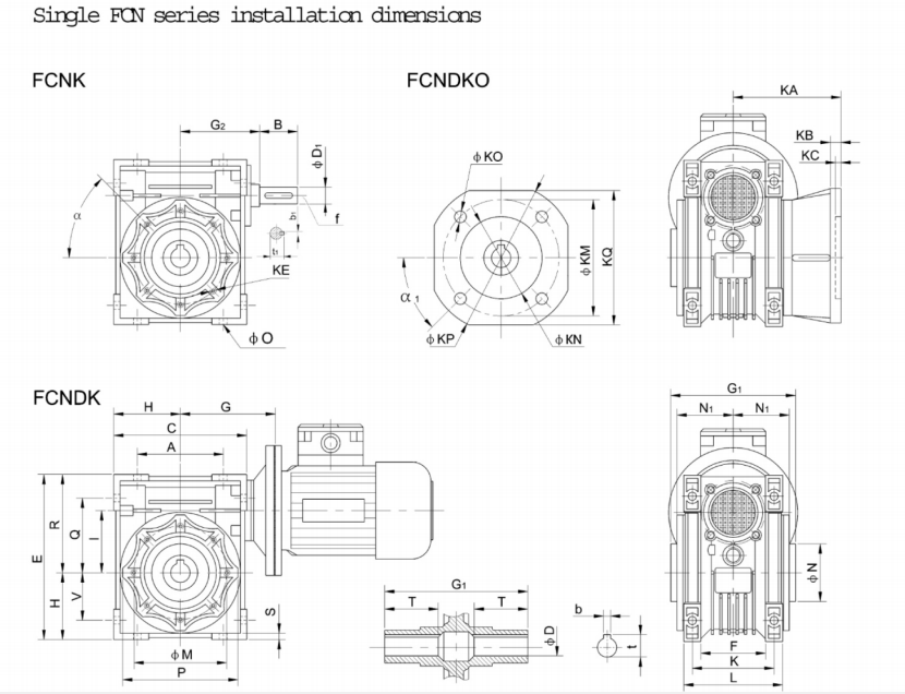
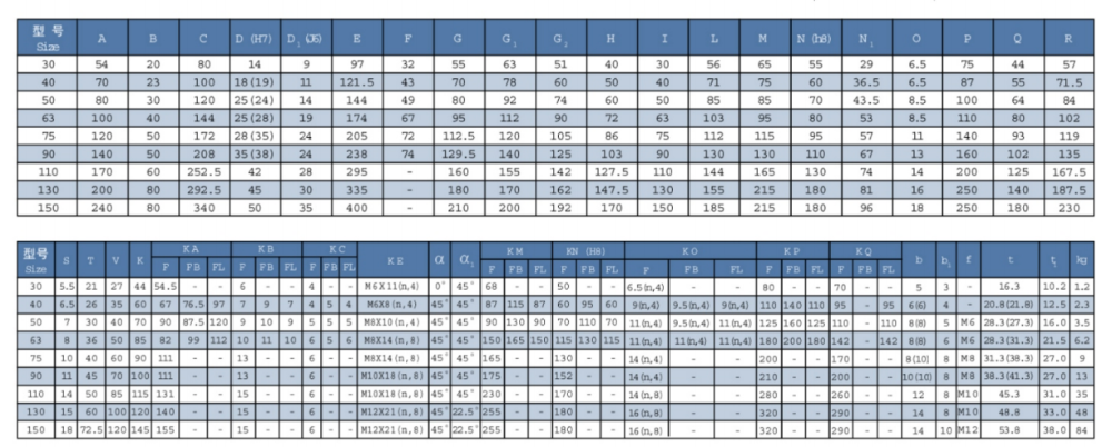
Packing & Supply
Packing Pictures of Worm Equipment Reducers
Inner Packing: PP bag with carton
Outer Packing: Wooden scenario
Shipment: 14-20 times upon receiviTo eradicate make contact with-sample inconsistencies, EPT produced an automated centering machine that correctly actions every single worm and gear subassembly, as nicely as the reducer housing and bearing handles. A pc data the info and calculates the thickness and location of shims needed to exactly middle the gear below the worm shaft and, at the exact same time, provides the appropriate finish 1play for the output tapered-roller bearings. This maximizes working efficiency and minimizes temperature rise.ng the deposit.

Related Products
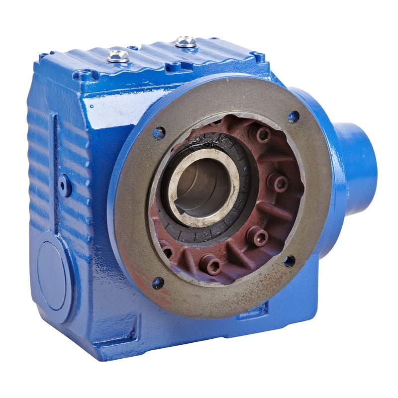
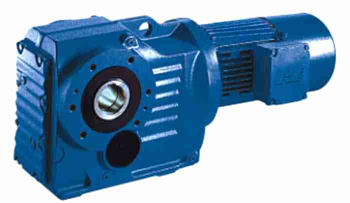
SEW Kind Gearbox with Motor
FR Helical Gearbox with Motor
Solid Iron Worm Gearbox
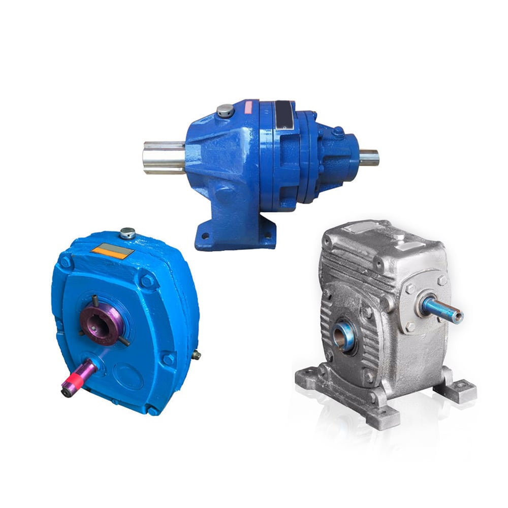
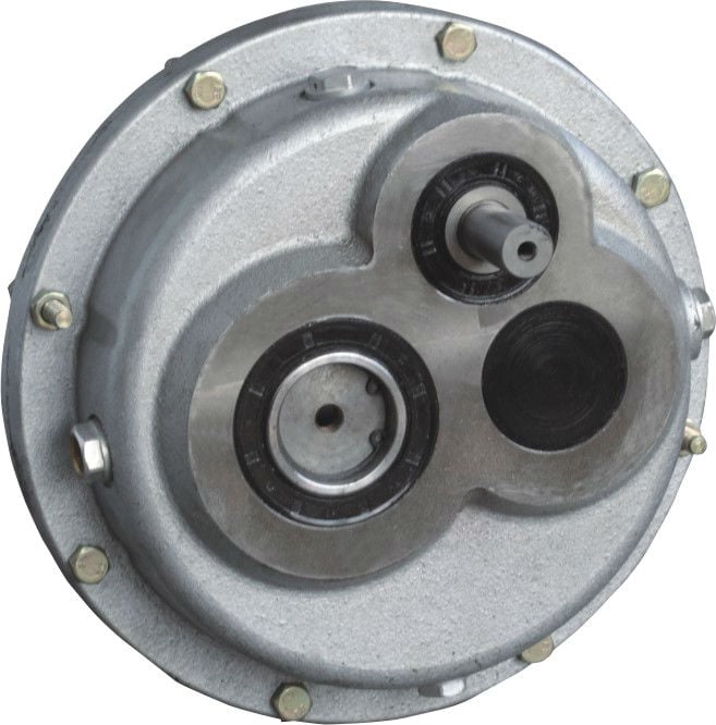
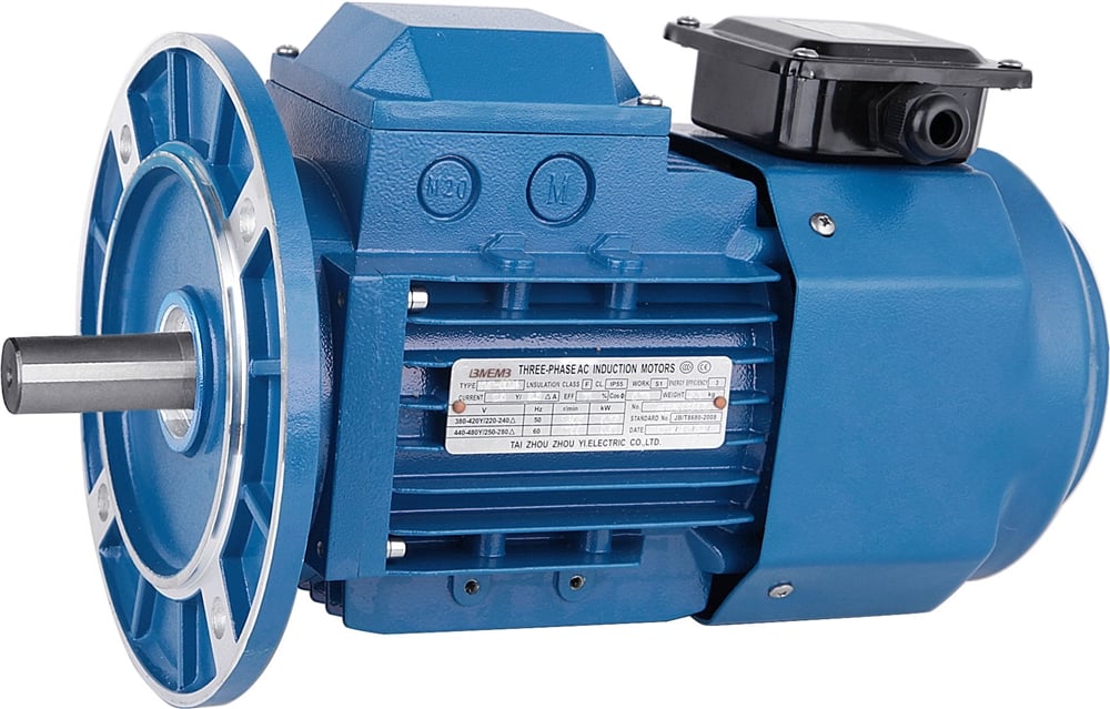
Bonfiglio Sort Shaft Mounted Gearbox
SMR Shaft Mounted Gearbox
Dodge TXT Type Shaft Mounted Gearbox
About Us
Ever_electricity Group is the first and premier worm gearbox maker in China, set up in 1976, specialising in the generation of a wide range of transmission machinery. With more than forty many years knowledge in the market, our assets now overall 117.2 million dollars, and we have 2 subsidiary organizations, 8 holding businesses, and twelve joint-inventory firms.
We can make four hundred,000 models of worm geSFI M100 PTO AdapterAs a precautionary measure, it is a good concept to purchase a PTO adapter to ensure compatibility with your certain tractor model.arboxes, 100,000 models of gear reducers, fifty,000 models of other speed reducers, one hundred fifty,000 models of versatile couplings, and a hundred,000 units of pace-reducer add-ons every single year.
70% of our items have been exported to forty a lot more nations, and our customers occur from Italy, Germany, United states of america, Canada, Spain, United kingdom, India, Mexico, Brazil, Argentina, Turkey, Singapore and other principal industrial countries. thirty% of them are OEM made for direct makers of other goods.
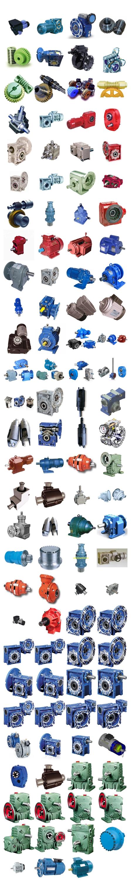
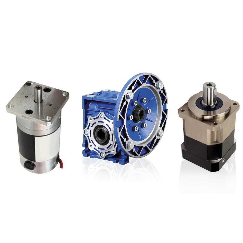
FAQ
Q1. Is your quality very good?
A1: Good quality never explain to lies, we’re the premier company and exporter of worm equipment reducer in Asia, the very first reducers and gearboxes company in China, who has been given license since 1993. Also, we had achieved ISO9001 and CE Certification amid all producers.
Q2. How is your cost? Can you provide any price reduction?
A2: We will give the greatest cost we can foundation on your needs and the quantities.
Q3. Do you offer any visiting?
A3: Our firm is located in XiHu HangZhou Zhejiang Province. TYes! We sincerely invite you to check out us! We can choose you from airport, railway station and so on. Also, we can organize housing for you. Make sure you let us know in sophisticated.
This fall. When is the best time to make contact with you?
A4: You can get in touch with us by e mail any time, we will reply you ASAP. If you want get in touch with by mobile phone, our doing work hour is Mon-Sat 9am-17:30pm.
Make contact with
At any time_electrical power Group
Deal with: No.789-B8Shenhua Road, XiHu Dsitriction Enco&Tech Advancement Zone HangZhou Metropolis, ZJ, P.R.
Tel: 0086-571-88220971/Mob: +86 13083988828
WhatsApp/Skype: +86 13083988828
Site: www.hzpt.com


