Product Description
Product Description
Warranty
1 Year
Applicable Industries
Hotels, Garment Shops, Building Material Shops, Manufacturing Plant, Machinery Repair Shops, Food & Beverage Factory, Farms, Restaurant, Home Use, Retail, Food Shop, Printing Shops, Construction works , Energy & Mining, Food & Beverage Shops, Other, Advertising Company
Weight (KG)
1
Showroom Location
Viet Nam
Video outgoing-inspection
Provided
Machinery Test Report
Provided
Marketing Type
Ordinary Product
Warranty of core components
1 Year
Core Components
PLC, Engine, Bearing, Gearbox, Motor, Pressure vessel, Gear, Pump
Material
steel
Place of CHINAMFG
ZheJiang , China
Condition
New
Structure
Shaft
Coatings
Customized
Torque Capacity
Customized
Model Number
Customized
Brand Name
NON
Description
Shaft
Machining equipment
CNC mill,lathe and grind machine
Material
stainless steel, aluminium, carbon
Surface
Grinding and polishing
Shape
Customized
Sampling time
10days
Production time
20days
Packing
Protective packing
Tolerance
±0.001
OEM
Welcome
Production Process
Company Profile
HangZhou HUANENGDA SPRING CO.,LTD
HangZhou HuaNengDa Spring Co., Ltd. is located in Tong ‘an District, HangZhou City, ZheJiang Province, China. It is a hardware factory specializing in R&D design, manufacture and sales of precision components. The company introduces domestic and foreign advanced equipment and production technology, adopts CNC high-precision computer machine, compression spring machine, CNC five-axis linkage machining center, CNC turning and milling compound, 300 tons of punch and other mechanical equipment,and employs senior engineers with more than 10 years of work experience to debug mechanical equipment and customize production.
With the business philosophy of honesty, pragmatism and excellence, HuaNengDa Spring Company is dedicated to serving customers at home and abroad. We hope that the products of HuaNengDa will help your business to be more brilliant, let us build a bright future in the high-tech era!
The testimony is pragmatic and the attitude of the people. Quality service is the pursuit of the people!
Factory Workshop
Production Procedur
Quality Inspection
Packing And Shipping
Our Service
FAQ
1.Small order quantity is workable
From the initial sample design of the spring to the mass production of the springs, we can quickly reach your manufacturing goals and immediately provide the best products because we have an excellent production management system and expertly trained technical personnel.
2.Committed to high quality production
To keep HuaNengDa Springs at the forefront of the industry, we have implemented a stringent internal quality control system and regularly import the latest manufacturing equipment and instruments. Through our precise manufacturing technology and expert mold making process, we provide our customers with the best products and service.
3.Efficiency in manufacturing
Our company’s machinery and equipment are controlled by CNC computers. In order to respond to international needs and standards, we continuously update and upgrade our equipment every year. Our machines effectively increase production capacity and save on manufacturing costs. The manufacturing department is the most important core of the whole company and by treating it with utmost importance, we reap great benefits in manufacturing efficiency.
4.Excellent customization services
HuaNengDa’s R&D team designs and completes customized products according to the needs of customers. From the selection of materials to the function of the products, we can design and develop products to suite different customers’ requirements. We are constantly involving ourselves in all aspects of the industry because only by having a complete view and analysis of the industry, can there be innovative breakthroughs.
Payment term
*T/T : 30% pre T/T, 70% before delivery.
*Trade Assurance
Service
*Delivery on time.
*Shipped by a convenient and cost-effective way.
*Good after-selling, 24 hours service for you.
Packing
*A: Poly bag, Plstic tray ,small box, carton.
*B: According to customers’ requirements.
Delivery
*Sample: 7-10 days after deposit received.
*Batch goods: 12-15 days after samples approved. /* March 10, 2571 17:59:20 */!function(){function s(e,r){var a,o={};try{e&&e.split(“,”).forEach(function(e,t){e&&(a=e.match(/(.*?):(.*)$/))&&1
| Condition: | New |
|---|---|
| Certification: | ISO9001 |
| Standard: | DIN, ASTM, GOST, GB, JIS, ANSI, BS |
| Customized: | Customized |
| Material: | Steel,Stainless Steel,Iron |
| Application: | Metal Processing Machinery Parts |
| Samples: |
US$ 10/Piece
1 Piece(Min.Order) | |
|---|
| Customization: |
Available
| Customized Request |
|---|

What safety considerations should be kept in mind when working with spline shafts?
Working with spline shafts requires adherence to certain safety considerations to ensure the well-being of personnel and the proper functioning of the machinery or equipment. Here’s a detailed explanation:
1. Personal Protective Equipment (PPE):
When working with spline shafts, individuals should wear appropriate personal protective equipment, including safety glasses, gloves, and protective clothing. PPE helps protect against potential hazards such as flying debris, sharp edges, or contact with lubricants.
2. Lockout/Tagout Procedures:
Prior to performing any maintenance or repair work on machinery or equipment involving spline shafts, proper lockout/tagout procedures should be followed. This involves isolating the power source, de-energizing the system, and securing it with lockout devices or tags to prevent accidental startup or release of stored energy.
3. Training and Competence:
Only trained and competent personnel should work with spline shafts. They should have a thorough understanding of the machinery or equipment, including the operation, maintenance, and safety procedures specific to spline shafts. Adequate training and knowledge help minimize the risk of accidents or improper handling.
4. Proper Handling and Lifting Techniques:
When moving or lifting machinery components that include spline shafts, proper techniques should be employed. This includes using appropriate lifting equipment, maintaining a stable posture, and avoiding sudden movements that could cause strain or injury.
5. Inspection and Maintenance:
Spline shafts should be regularly inspected for signs of wear, damage, or misalignment. Any abnormalities should be addressed promptly by qualified personnel. Routine maintenance, such as lubrication and cleaning, should be performed according to the manufacturer’s recommendations to ensure optimal performance and longevity.
6. Correct Installation and Alignment:
During installation or replacement of spline shafts, proper alignment and fit should be ensured. The shafts should be correctly seated and engaged with the mating components, following the manufacturer’s guidelines. Improper installation or misalignment can lead to premature wear, excessive stress, or failure of the spline shafts.
7. Hazardous Environments:
When spline shafts are used in hazardous environments, such as those with flammable substances, extreme temperatures, or high vibrations, additional safety measures may be required. These may include explosion-proof enclosures, temperature monitoring, or vibration damping systems.
8. Emergency Procedures:
Emergency procedures should be established and communicated to all personnel working with spline shafts. This includes knowing the location of emergency stops, emergency shutdown procedures, and the contact information for emergency response personnel.
9. Manufacturer’s Guidelines:
It is essential to follow the manufacturer’s guidelines and recommendations regarding the installation, operation, and maintenance of spline shafts. The manufacturer’s instructions provide specific safety information and precautions tailored to their product.
By taking these safety considerations into account and implementing appropriate measures, the risks associated with working with spline shafts can be minimized. Safety should always be a top priority when dealing with machinery or equipment that incorporates spline shafts.

How do spline shafts handle variations in load capacity and weight?
Spline shafts are designed to handle variations in load capacity and weight in mechanical systems. Here’s how they accomplish this:
1. Material Selection:
Spline shafts are typically made from high-strength materials such as steel or alloy, chosen for their ability to withstand heavy loads and provide durability. The selection of materials takes into account factors such as tensile strength, yield strength, and fatigue resistance to ensure the shaft can handle variations in load capacity and weight.
2. Engineering Design:
Spline shafts are designed with consideration for the anticipated loads and weights they will encounter. The dimensions, profile, and number of splines are determined based on the expected torque requirements and the magnitude of the applied loads. By carefully engineering the design, spline shafts can handle variations in load capacity and weight while maintaining structural integrity and reliable performance.
3. Load Distribution:
The interlocking engagement of spline shafts allows for effective load distribution along the length of the shaft. This helps distribute the applied loads evenly, preventing localized stress concentrations and minimizing the risk of deformation or failure. By distributing the load, spline shafts can handle variations in load capacity and weight without compromising their performance.
4. Structural Reinforcement:
In applications with higher load capacities or heavier weights, spline shafts may incorporate additional structural features to enhance their strength. This can include thicker spline teeth, larger spline diameters, or reinforced sections along the shaft. By reinforcing critical areas, spline shafts can handle increased loads and weights while maintaining their integrity.
5. Lubrication and Surface Treatment:
Proper lubrication is essential for spline shafts to handle variations in load capacity and weight. Lubricants reduce friction between the mating surfaces, minimizing wear and preventing premature failure. Additionally, surface treatments such as coatings or heat treatments can enhance the hardness and wear resistance of the spline shaft, improving its ability to handle varying loads and weights.
6. Testing and Validation:
Spline shafts undergo rigorous testing and validation to ensure they meet the specified load capacity and weight requirements. This may involve laboratory testing, simulation analysis, or field testing under real-world conditions. By subjecting spline shafts to thorough testing, manufacturers can verify their performance and ensure they can handle variations in load capacity and weight.
Overall, spline shafts are designed and engineered to handle variations in load capacity and weight by utilizing appropriate materials, optimizing the design, distributing loads effectively, incorporating structural reinforcement when necessary, implementing proper lubrication and surface treatments, and conducting thorough testing and validation. These measures enable spline shafts to reliably transmit torque and handle varying loads in diverse mechanical applications.

Can you explain the common applications of spline shafts in machinery?
Spline shafts have various common applications in machinery where torque transmission, relative movement, and load distribution are essential. Here’s a detailed explanation:
1. Gearboxes and Transmissions:
Spline shafts are commonly used in gearboxes and transmissions where they facilitate the transmission of torque from the input shaft to the output shaft. The splines on the shaft engage with corresponding splines on the gears, allowing for precise torque transfer and accommodating relative movement between the gears.
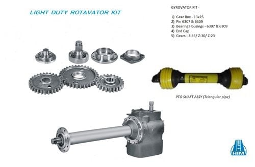
2. Power Take-Off (PTO) Units:
In agricultural and industrial machinery, spline shafts are employed in power take-off (PTO) units. PTO units allow the transfer of power from the engine to auxiliary equipment, such as pumps, generators, or farm implements. Spline shafts enable the torque transfer and accommodate the relative movement required for PTO operation.
3. Steering Systems:
Spline shafts play a crucial role in steering systems, especially in vehicles. They are used in steering columns to transmit torque from the steering wheel to the steering rack or gearbox. The splines on the shaft ensure precise torque transfer while allowing for the axial movement required for steering wheel adjustment.
4. Machine Tools:
Spline shafts find applications in machine tools such as milling machines, lathes, and grinding machines. They are used to transmit torque and enable the relative movement required for tool positioning, feed control, and spindle rotation. Spline shafts ensure accurate and controlled movement of the machine tool components.
5. Industrial Pumps and Compressors:
Spline shafts are utilized in various types of pumps and compressors, including centrifugal pumps, gear pumps, and reciprocating compressors. They transmit torque from the driver (such as an electric motor or an engine) to the impeller or rotor, enabling fluid or gas transfer. Spline shafts accommodate the axial or radial movement caused by thermal expansion or misalignment.
6. Printing and Packaging Machinery:
Spline shafts are integral components in printing and packaging machinery. They are used in processes such as web handling, where precise torque transmission and relative movement are required for tasks like tension control, registration, and material feeding. Spline shafts ensure accurate and synchronized movement of the printing and packaging elements.
7. Aerospace and Defense Systems:
In the aerospace and defense industries, spline shafts are utilized in various applications, including aircraft landing gear systems, missile guidance systems, and helicopter rotor systems. They enable torque transmission, accommodate relative movement, and ensure precise control in critical aerospace and defense mechanisms.
8. Construction and Earthmoving Equipment:
Spline shafts are employed in construction and earthmoving equipment, such as excavators, bulldozers, and loaders. They are used in hydraulic systems to transmit torque from the hydraulic motor to the driven components, such as the digger arm or the bucket. Spline shafts enable efficient power transfer and allow for the articulation and movement of the equipment.
These are just a few examples of the common applications of spline shafts in machinery. Their versatility, torque transmission capabilities, and ability to accommodate relative movement make them essential components in various industries where precise power transfer and flexibility are required.


editor by CX 2024-02-24
China Standard Custom Precision Engine Shafts Supplier Machining Stainless Carbon Linear Flexible Spline Motor Spindle Axle Steel Shaft
Product Description
Product Description
|
Company Profile
HangZhou Xihu (West Lake) Dis. Machinery Manufacture Co., Ltd., located in HangZhou, “China’s ancient copper capital”, is a “national high-tech enterprise”. At the beginning of its establishment, the company adhering to the “to provide clients with high quality products, to provide timely service” concept, adhere to the “everything for the customer, make customer excellent supplier” for the mission.
Certifications
Q: Where is your company located ?
A: HangZhou ZheJiang .
Q: How could l get a sample?
A: Before we received the first order, please afford the sample cost and express fee. we will return the sample cost back
to you within your first order.
Q: Sample time?
A: Existing items: within 20-60 days.
Q: Whether you could make our brand on your products?
A: Yes. We can print your Logo on both the products and the packages if you can meet our MOQ.
Q: How to guarantee the quality of your products?
A: 1) stict detection during production. 2) Strict completely inspecion on products before shipment and intact product
packaging ensured.
Q: lf my drawings are safe?
A: Yes ,we can CHINAMFG NDA.
/* March 10, 2571 17:59:20 */!function(){function s(e,r){var a,o={};try{e&&e.split(“,”).forEach(function(e,t){e&&(a=e.match(/(.*?):(.*)$/))&&1
| Material: | Carbon Steel |
|---|---|
| Load: | Drive Shaft |
| Stiffness & Flexibility: | Stiffness / Rigid Axle |
| Journal Diameter Dimensional Accuracy: | OEM/ODM/Customized |
| Axis Shape: | Straight Shaft |
| Shaft Shape: | OEM/ODM/Customized |
| Samples: |
US$ 100/Piece
1 Piece(Min.Order) | |
|---|
| Customization: |
Available
| Customized Request |
|---|

How does the design of a spline shaft affect its performance?
The design of a spline shaft plays a crucial role in determining its performance characteristics. Here’s a detailed explanation:
1. Torque Transmission:
The design of the spline shaft directly affects its ability to transmit torque efficiently. Factors such as the spline profile, number of splines, and engagement length influence the torque-carrying capacity of the shaft. A well-designed spline profile with optimized dimensions ensures maximum contact area and load distribution, resulting in improved torque transmission.
2. Load Distribution:
A properly designed spline shaft distributes the applied load evenly across the engagement surfaces. This helps to minimize stress concentrations and prevents localized wear or failure. The design should consider factors such as spline profile geometry, tooth form, and surface finish to achieve optimal load distribution and enhance the overall performance of the shaft.
3. Misalignment Compensation:
Spline shafts can accommodate a certain degree of misalignment between the mating components. The design of the spline profile can incorporate features that allow for angular or parallel misalignment, ensuring effective power transmission even under misaligned conditions. Proper design considerations help maintain smooth operation and prevent excessive stress or premature failure.
4. Torsional Stiffness:
The design of the spline shaft influences its torsional stiffness, which is the resistance to twisting under torque. A stiffer shaft design reduces torsional deflection, improves torque response, and enhances the system’s overall performance. The shaft material, diameter, and spline profile all contribute to achieving the desired torsional stiffness.
5. Fatigue Resistance:
The design of the spline shaft should consider fatigue resistance to ensure long-term durability. Fatigue failure can occur due to repeated or cyclic loading. Proper design practices, such as optimizing the spline profile, selecting appropriate materials, and incorporating suitable surface treatments, can enhance the fatigue resistance of the shaft and extend its service life.
6. Surface Finish and Lubrication:
The surface finish of the spline shaft and the lubrication used significantly impact its performance. A smooth surface finish reduces friction, wear, and the potential for corrosion. Proper lubrication ensures adequate film formation, reduces heat generation, and minimizes wear. The design should incorporate considerations for surface finish requirements and lubrication provisions to optimize the shaft’s performance.
7. Environmental Considerations:
The design should take into account the specific environmental conditions in which the spline shaft will operate. Factors such as temperature, humidity, exposure to chemicals, or abrasive particles can affect the shaft’s performance and longevity. Suitable material selection, surface treatments, and sealing mechanisms can be incorporated into the design to withstand the environmental challenges.
8. Manufacturing Feasibility:
The design of the spline shaft should also consider manufacturing feasibility and cost-effectiveness. Complex designs may be challenging to produce or require specialized manufacturing processes, resulting in increased production costs. Balancing design complexity with manufacturability is crucial to ensure a practical and efficient manufacturing process.
By considering these design factors, engineers can optimize the performance of spline shafts, resulting in enhanced torque transmission, improved load distribution, misalignment compensation, torsional stiffness, fatigue resistance, surface finish, and environmental compatibility. A well-designed spline shaft contributes to the overall efficiency, reliability, and longevity of the mechanical system in which it is used.

How do spline shafts handle variations in environmental conditions?
Spline shafts are designed to handle variations in environmental conditions and maintain their performance and reliability. Here’s a detailed explanation:
1. Temperature Variations:
Spline shafts are engineered to withstand a wide range of temperature variations. They are constructed from materials that exhibit good thermal stability, such as high-grade steels or alloys. These materials have low coefficients of thermal expansion, minimizing the effects of temperature changes on the shaft’s dimensional stability. Additionally, proper lubrication with temperature-resistant lubricants helps reduce friction and wear in the spline engagement, even under extreme temperature conditions.
2. Moisture and Corrosion Resistance:
Spline shafts can be designed to resist moisture and corrosion, ensuring their performance in humid or corrosive environments. Protective coatings, such as platings or surface treatments, can be applied to the shaft’s surfaces to enhance their resistance to moisture, oxidation, and corrosion. Additionally, selecting materials with inherent corrosion resistance, such as stainless steel or specialized alloys, can further enhance the spline shaft’s ability to handle environmental conditions.
3. Dust and Contaminant Protection:
Spline shafts used in environments with high levels of dust, dirt, or contaminants can be equipped with protective measures. Seals, gaskets, or covers can be employed to prevent the ingress of particles into the spline engagement. These protective measures help maintain the integrity of the spline profile, minimize wear, and ensure smooth operation even in dirty or dusty conditions.
4. Lubrication and Maintenance:
Proper lubrication is essential for the reliable operation of spline shafts, especially in challenging environmental conditions. Lubricants with appropriate viscosity and additives can be selected to provide effective lubrication and protection against wear, friction, and corrosion. Regular maintenance and lubrication intervals should be followed to ensure optimal performance and longevity of the spline shaft.
5. Shock and Vibration Resistance:
Spline shafts are designed to withstand shock and vibration encountered in various applications. The spline engagement and shaft design can incorporate features such as tighter tolerances, increased contact area, or damping elements to minimize the effects of shock and vibration. Additionally, proper fastening and mounting techniques help secure the shaft and reduce the risk of loosening or failure due to dynamic loads.
6. Environmental Sealing:
In certain applications where spline shafts are exposed to harsh environmental conditions, such as underwater or in chemical environments, environmental sealing can be employed. Sealing methods such as O-rings, gaskets, or specialized seals provide an additional barrier against external elements, ensuring the integrity and performance of the spline shaft.
7. Compliance with Standards:
Spline shafts used in specific industries or applications may need to comply with industry standards or regulations regarding environmental conditions. Manufacturers can design and test their spline shafts to meet these requirements, ensuring that the shafts can handle the specified environmental conditions and perform reliably.
By incorporating design considerations, appropriate materials, protective coatings, lubrication, and maintenance practices, spline shafts can effectively handle variations in environmental conditions. This enables them to maintain their functionality, performance, and longevity even in challenging operating environments.

In which industries are spline shafts typically used?
Spline shafts find applications in a wide range of industries where torque transmission, relative movement, and load distribution are critical. Here’s a detailed explanation:
1. Automotive Industry:
The automotive industry extensively uses spline shafts in various components and systems. They are found in transmissions, drivelines, steering systems, differentials, and axle assemblies. Spline shafts enable the transmission of torque, accommodate relative movement, and ensure efficient power transfer in vehicles.
2. Aerospace and Defense Industry:
Spline shafts are essential in the aerospace and defense industry. They are used in aircraft landing gear systems, actuation mechanisms, missile guidance systems, engine components, and rotor assemblies. The aerospace and defense sector relies on spline shafts for precise torque transfer, relative movement accommodation, and critical control mechanisms.
3. Industrial Machinery and Equipment:
Spline shafts are widely employed in industrial machinery and equipment. They are used in gearboxes, machine tools, pumps, compressors, conveyors, printing machinery, and packaging equipment. Spline shafts enable torque transmission, accommodate misalignments and vibrations, and ensure accurate movement and synchronization of machine components.
4. Agriculture and Farming:
The agriculture and farming industry extensively uses spline shafts in equipment such as tractors, harvesters, and agricultural implements. Spline shafts are found in power take-off (PTO) units, transmission systems, hydraulic mechanisms, and steering systems. They enable torque transfer, accommodate relative movement, and provide flexibility in agricultural machinery.
5. Construction and Mining:
In the construction and mining industries, spline shafts are used in equipment such as excavators, loaders, bulldozers, and drilling rigs. They are found in hydraulic systems, power transmission systems, and articulated mechanisms. Spline shafts facilitate torque transmission, accommodate misalignments, and enable efficient power transfer in heavy-duty machinery.
6. Marine and Offshore:
Spline shafts have applications in the marine and offshore industry. They are used in propulsion systems, thrusters, rudders, winches, and marine pumps. Spline shafts enable torque transmission in marine vessels and offshore equipment, accommodating axial and radial movement, and ensuring reliable power transfer.
7. Energy and Power Generation:
Spline shafts are utilized in the energy and power generation sector. They are found in turbines, generators, compressors, and other rotating equipment. Spline shafts enable torque transmission and accommodate relative movement in power generation systems, ensuring efficient and reliable operation.
8. Rail and Transportation:
Spline shafts are employed in the rail and transportation industry. They are found in locomotives, railcar systems, and suspension mechanisms. Spline shafts enable torque transfer, accommodate movement and vibrations, and ensure precise control in rail and transportation applications.
These are just a few examples of the industries where spline shafts are typically used. Their versatility, torque transmission capabilities, and ability to accommodate relative movement make them vital components in various sectors that rely on efficient power transfer, flexibility, and precise control.
editor by CX 2024-01-08
China High Quality Gicl Series Stainless Steel Curved Teeth Drum Spline Motor pump Flexible Marine Drive Shaft Gear Coupling drive shaft adapter
Guarantee: 1 years
Applicable Industries: Equipment Restore Outlets, Other
Custom-made help: OEM
Construction: Gear
Versatile or Rigid: Rigid, Each
Normal or Nonstandard: Normal, Common
Substance: Stainless steel
Entire body Substance: Metal
Bore kind: Customised
Floor Therapy: Blackened
Packaging Details: As for each consumer need
Port: nhava sheva, mundhra
| Product Title | Gear Coupling |
| Brand Name | Aariv Precision |
Standard Length Splined Shafts
Standard Length Splined Shafts are made from Mild Steel and are perfect for most repair jobs, custom machinery building, and many other applications. All stock splined shafts are 2-3/4 inches in length, and full splines are available in any length, with additional materials and working lengths available upon request and quotation. CZPT Manufacturing Company is proud to offer these standard length shafts.
Disc brake mounting interfaces that are splined
There are two common disc brake mounting interfaces, splined and center lock. Disc brakes with splined interfaces are more common. They are usually easier to install. The center lock system requires a tool to remove the locking ring on the disc hub. Six-bolt rotors are easier to install and require only six bolts. The center lock system is commonly used with performance road bikes.
Post mount disc brakes require a post mount adapter, while flat mount disc brakes do not. Post mount adapters are more common and are used for carbon mountain bikes, while flat mount interfaces are becoming the norm on road and gravel bikes. All disc brake adapters are adjustable for rotor size, though. Road bikes usually use 160mm rotors while mountain bikes use rotors that are 180mm or 200mm.
Disc brake mounting interfaces that are helical splined
A helical splined disc brake mounting interface is designed with a splined connection between the hub and brake disc. This splined connection allows for a relatively large amount of radial and rotational displacement between the disc and hub. A loosely splined interface can cause a rattling noise due to the movement of the disc in relation to the hub.
The splines on the brake disc and hub are connected via an air gap. The air gap helps reduce heat conduction from the brake disc to the hub. The present invention addresses problems of noise, heat, and retraction of brake discs at the release of the brake. It also addresses issues with skewing and dragging. If you’re unsure whether this type of mounting interface is right for you, consult your mechanic.
Disc brake mounting interfaces that are helix-splined may be used in conjunction with other components of a wheel. They are particularly useful in disc brake mounting interfaces for hub-to-hub assemblies. The spacer elements, which are preferably located circumferentially, provide substantially the same function no matter how the brake disc rotates. Preferably, three spacer elements are located around the brake disc. Each of these spacer elements has equal clearance between the splines of the brake disc and the hub.
Spacer elements 6 include a helical spring portion 6.1 and extensions in tangential directions that terminate in hooks 6.4. These hooks abut against the brake disc 1 in both directions. The helical spring portion 5.1 and 6.1 have stiffness enough to absorb radial impacts. The spacer elements are arranged around the circumference of the intermeshing zone.
A helical splined disc mount includes a stabilizing element formed as a helical spring. The helical spring extends to the disc’s splines and teeth. The ends of the extension extend in opposite directions, while brackets at each end engage with the disc’s splines and teeth. This stabilizing element is positioned axially over the disc’s width.
Helical splined disc brake mounting interfaces are popular in bicycles and road bicycles. They’re a reliable, durable way to mount your brakes. Splines are widely used in aerospace, and have a higher fatigue life and reliability. The interfaces between the splined disc brake and BB spindle are made from aluminum and acetate.
As the splined hub mounts the disc in a helical fashion, the spring wire and disc 2 will be positioned in close contact. As the spring wire contacts the disc, it creates friction forces that are evenly distributed throughout the disc. This allows for a wide range of axial motion. Disc brake mounting interfaces that are helical splined have higher strength and stiffness than their counterparts.
Disc brake mounting interfaces that are helically splined can have a wide range of splined surfaces. The splined surfaces are the most common type of disc brake mounting interfaces. They are typically made of stainless steel or aluminum and can be used for a variety of applications. However, a splined disc mount will not support a disc with an oversized brake caliper.


editor by czh 2023-02-18
China CNC Electroplated Mirror Stainless Steel Long Shaft Parts Flexible Shaft OEM Customized Automatic Material Origin Spline CNC drive shaft parts
Error:获取返回内容失败,
Your session has expired. Please reauthenticate.
Stiffness and Torsional Vibration of Spline-Couplings
In this paper, we describe some basic characteristics of spline-coupling and examine its torsional vibration behavior. We also explore the effect of spline misalignment on rotor-spline coupling. These results will assist in the design of improved spline-coupling systems for various applications. The results are presented in Table 1.
Stiffness of spline-coupling
The stiffness of a spline-coupling is a function of the meshing force between the splines in a rotor-spline coupling system and the static vibration displacement. The meshing force depends on the coupling parameters such as the transmitting torque and the spline thickness. It increases nonlinearly with the spline thickness.
A simplified spline-coupling model can be used to evaluate the load distribution of splines under vibration and transient loads. The axle spline sleeve is displaced a z-direction and a resistance moment T is applied to the outer face of the sleeve. This simple model can satisfy a wide range of engineering requirements but may suffer from complex loading conditions. Its asymmetric clearance may affect its engagement behavior and stress distribution patterns.
The results of the simulations show that the maximum vibration acceleration in both Figures 10 and 22 was 3.03 g/s. This results indicate that a misalignment in the circumferential direction increases the instantaneous impact. Asymmetry in the coupling geometry is also found in the meshing. The right-side spline’s teeth mesh tightly while those on the left side are misaligned.
Considering the spline-coupling geometry, a semi-analytical model is used to compute stiffness. This model is a simplified form of a classical spline-coupling model, with submatrices defining the shape and stiffness of the joint. As the design clearance is a known value, the stiffness of a spline-coupling system can be analyzed using the same formula.
The results of the simulations also show that the spline-coupling system can be modeled using MASTA, a high-level commercial CAE tool for transmission analysis. In this case, the spline segments were modeled as a series of spline segments with variable stiffness, which was calculated based on the initial gap between spline teeth. Then, the spline segments were modelled as a series of splines of increasing stiffness, accounting for different manufacturing variations. The resulting analysis of the spline-coupling geometry is compared to those of the finite-element approach.
Despite the high stiffness of a spline-coupling system, the contact status of the contact surfaces often changes. In addition, spline coupling affects the lateral vibration and deformation of the rotor. However, stiffness nonlinearity is not well studied in splined rotors because of the lack of a fully analytical model.
Characteristics of spline-coupling
The study of spline-coupling involves a number of design factors. These include weight, materials, and performance requirements. Weight is particularly important in the aeronautics field. Weight is often an issue for design engineers because materials have varying dimensional stability, weight, and durability. Additionally, space constraints and other configuration restrictions may require the use of spline-couplings in certain applications.
The main parameters to consider for any spline-coupling design are the maximum principal stress, the maldistribution factor, and the maximum tooth-bearing stress. The magnitude of each of these parameters must be smaller than or equal to the external spline diameter, in order to provide stability. The outer diameter of the spline must be at least four inches larger than the inner diameter of the spline.
Once the physical design is validated, the spline coupling knowledge base is created. This model is pre-programmed and stores the design parameter signals, including performance and manufacturing constraints. It then compares the parameter values to the design rule signals, and constructs a geometric representation of the spline coupling. A visual model is created from the input signals, and can be manipulated by changing different parameters and specifications.
The stiffness of a spline joint is another important parameter for determining the spline-coupling stiffness. The stiffness distribution of the spline joint affects the rotor’s lateral vibration and deformation. A finite element method is a useful technique for obtaining lateral stiffness of spline joints. This method involves many mesh refinements and requires a high computational cost.
The diameter of the spline-coupling must be large enough to transmit the torque. A spline with a larger diameter may have greater torque-transmitting capacity because it has a smaller circumference. However, the larger diameter of a spline is thinner than the shaft, and the latter may be more suitable if the torque is spread over a greater number of teeth.
Spline-couplings are classified according to their tooth profile along the axial and radial directions. The radial and axial tooth profiles affect the component’s behavior and wear damage. Splines with a crowned tooth profile are prone to angular misalignment. Typically, these spline-couplings are oversized to ensure durability and safety.
Stiffness of spline-coupling in torsional vibration analysis
This article presents a general framework for the study of torsional vibration caused by the stiffness of spline-couplings in aero-engines. It is based on a previous study on spline-couplings. It is characterized by the following three factors: bending stiffness, total flexibility, and tangential stiffness. The first criterion is the equivalent diameter of external and internal splines. Both the spline-coupling stiffness and the displacement of splines are evaluated by using the derivative of the total flexibility.
The stiffness of a spline joint can vary based on the distribution of load along the spline. Variables affecting the stiffness of spline joints include the torque level, tooth indexing errors, and misalignment. To explore the effects of these variables, an analytical formula is developed. The method is applicable for various kinds of spline joints, such as splines with multiple components.
Despite the difficulty of calculating spline-coupling stiffness, it is possible to model the contact between the teeth of the shaft and the hub using an analytical approach. This approach helps in determining key magnitudes of coupling operation such as contact peak pressures, reaction moments, and angular momentum. This approach allows for accurate results for spline-couplings and is suitable for both torsional vibration and structural vibration analysis.
The stiffness of spline-coupling is commonly assumed to be rigid in dynamic models. However, various dynamic phenomena associated with spline joints must be captured in high-fidelity drivetrain models. To accomplish this, a general analytical stiffness formulation is proposed based on a semi-analytical spline load distribution model. The resulting stiffness matrix contains radial and tilting stiffness values as well as torsional stiffness. The analysis is further simplified with the blockwise inversion method.
It is essential to consider the torsional vibration of a power transmission system before selecting the coupling. An accurate analysis of torsional vibration is crucial for coupling safety. This article also discusses case studies of spline shaft wear and torsionally-induced failures. The discussion will conclude with the development of a robust and efficient method to simulate these problems in real-life scenarios.
Effect of spline misalignment on rotor-spline coupling
In this study, the effect of spline misalignment in rotor-spline coupling is investigated. The stability boundary and mechanism of rotor instability are analyzed. We find that the meshing force of a misaligned spline coupling increases nonlinearly with spline thickness. The results demonstrate that the misalignment is responsible for the instability of the rotor-spline coupling system.
An intentional spline misalignment is introduced to achieve an interference fit and zero backlash condition. This leads to uneven load distribution among the spline teeth. A further spline misalignment of 50um can result in rotor-spline coupling failure. The maximum tensile root stress shifted to the left under this condition.
Positive spline misalignment increases the gear mesh misalignment. Conversely, negative spline misalignment has no effect. The right-handed spline misalignment is opposite to the helix hand. The high contact area is moved from the center to the left side. In both cases, gear mesh is misaligned due to deflection and tilting of the gear under load.
This variation of the tooth surface is measured as the change in clearance in the transverse plain. The radial and axial clearance values are the same, while the difference between the two is less. In addition to the frictional force, the axial clearance of the splines is the same, which increases the gear mesh misalignment. Hence, the same procedure can be used to determine the frictional force of a rotor-spline coupling.
Gear mesh misalignment influences spline-rotor coupling performance. This misalignment changes the distribution of the gear mesh and alters contact and bending stresses. Therefore, it is essential to understand the effects of misalignment in spline couplings. Using a simplified system of helical gear pair, Hong et al. examined the load distribution along the tooth interface of the spline. This misalignment caused the flank contact pattern to change. The misaligned teeth exhibited deflection under load and developed a tilting moment on the gear.
The effect of spline misalignment in rotor-spline couplings is minimized by using a mechanism that reduces backlash. The mechanism comprises cooperably splined male and female members. One member is formed by two coaxially aligned splined segments with end surfaces shaped to engage in sliding relationship. The connecting device applies axial loads to these segments, causing them to rotate relative to one another.
editor by czh 2023-02-16
China Custom Precision Engine Shafts Supplier Machining Stainless Carbon Linear Flexible Spline Motor Spindle Axle Steel Shaft drive shaft axle
Condition: New
Warranty: 1 Year
Applicable Industries: Building Material Shops, Manufacturing Plant, Machinery Repair Shops, Construction works
Weight (KG): 1
Showroom Location: Germany
Video outgoing-inspection: Provided
Machinery Test Report: Provided
Marketing Type: Ordinary Product
Warranty of core components: 1 Year
Core Components: PLC, Engine, Bearing, Gearbox, Motor, Pressure vessel, Gear, Pump
Structure: Flexible
Material: steel, Stainless steel, Custom, Customized
Coatings: Custom
Torque Capacity: Custom
Model Number: Custom
Quality: OEM Standard
Service: OEM Customized Services
Delivery time: 7-25days
Surface: Perfect Appearance
Equipment: CNC Turning Milling Machining Equipments
Size: Customized Size
MOQ: 10pcs
Drawing Format: 2D/3D PDF/CAD/STEP
Tolerance: 0.003mm~0.005mm
Packaging Details: 1.Plastic bag or plastic wrap inside, carton outside2.The package of Brass Turning Machine Spare Parts as customers’ requirement
Port: HangZhou,HangZhou,Hong Kong
We can customize it according to your requirements,With the ability from design to drawing to production, we can provide you with a full range of services. Manufacturing Technique Grinding machine shopSpecializing in the production of various high-precision custom shaft parts German Zeiss CMM, to provide guarantee for your quality Professional quality inspection equipment and team to provide high-quality products
| Product Type | engine shaft, steel shaft, shafts for treadmills, flexible shaft |
| Surface Treatment | heat treatment |
| Drawing Format | PDF,DWG,step |
| Application | Automotive, Automation, Test systems, Sensors, Medical, Sports, Consumer, Home appliance,Electronic, Pumps, Computers, Power andenergy, Architecture, Printing, Food, Textile machinery, Optical, Lighting, Security and safety, AOI, CZPT equipment, etc. |
| Package | protective packing |
| sample | 7—10 days |
| Certificate | ISO,SGS |
| Production Capacity | 100,000 pieces per month |
| Our Service | CNC Machining,Plastic Injection,Stamping,Die Casting,Silicone And Rubber,Aluminum Extrusion,Mould Making,etc |
The Different Types of Splines in a Splined Shaft
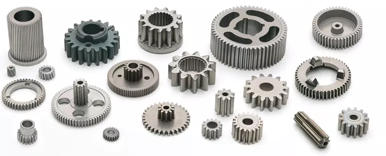
A splined shaft is a machine component with internal and external splines. The splines are formed in four different ways: Involute, Parallel, Serrated, and Ball. You can learn more about each type of spline in this article. When choosing a splined shaft, be sure to choose the right one for your application. Read on to learn about the different types of splines and how they affect the shaft’s performance.
Involute splines
Involute splines in a splined shaft are used to secure and extend mechanical assemblies. They are smooth, inwardly curving grooves that resist separation during operation. A shaft with involute splines is often longer than the shaft itself. This feature allows for more axial movement. This is beneficial for many applications, especially in a gearbox.
The involute spline is a shaped spline, similar to a parallel spline. It is angled and consists of teeth that create a spiral pattern that enables linear and rotatory motion. It is distinguished from other splines by the serrations on its flanks. It also has a flat top. It is a good option for couplers and other applications where angular movement is necessary.
Involute splines are also called involute teeth because of their shape. They are flat on the top and curved on the sides. These teeth can be either internal or external. As a result, involute splines provide greater surface contact, which helps reduce stress and fatigue. Regardless of the shape, involute splines are generally easy to machine and fit.
Involute splines are a type of splines that are used in splined shafts. These splines have different names, depending on their diameters. An example set of designations is for a 32-tooth male spline, a 2,500-tooth module, and a 30 degree pressure angle. An example of a female spline, a fillet root spline, is used to describe the diameter of the splined shaft.
The effective tooth thickness of splines is dependent on the number of keyways and the type of spline. Involute splines in splined shafts should be designed to engage 25 to 50 percent of the spline teeth during the coupling. Involute splines should be able to withstand the load without cracking.
Parallel splines
Parallel splines are formed on a splined shaft by putting one or more teeth into another. The male spline is positioned at the center of the female spline. The teeth of the male spline are also parallel to the shaft axis, but a common misalignment causes the splines to roll and tilt. This is common in many industrial applications, and there are a number of ways to improve the performance of splines.
Typically, parallel splines are used to reduce friction in a rotating part. The splines on a splined shaft are narrower on the end face than the interior, which makes them more prone to wear. This type of spline is used in a variety of industries, such as machinery, and it also allows for greater efficiency when transmitting torque.
Involute splines on a splined shaft are the most common. They have equally spaced teeth, and are therefore less likely to crack due to fatigue. They also tend to be easy to cut and fit. However, they are not the best type of spline. It is important to understand the difference between parallel and involute splines before deciding on which spline to use.
The difference between splined and involute splines is the size of the grooves. Involute splines are generally larger than parallel splines. These types of splines provide more torque to the gear teeth and reduce stress during operation. They are also more durable and have a longer life span. And because they are used on farm machinery, they are essential in this type of application.
Serrated splines
A Serrated Splined Shaft has several advantages. This type of shaft is highly adjustable. Its large number of teeth allows large torques, and its shorter tooth width allows for greater adjustment. These features make this type of shaft an ideal choice for applications where accuracy is critical. Listed below are some of the benefits of this type of shaft. These benefits are just a few of the advantages. Learn more about this type of shaft.
The process of hobbing is inexpensive and highly accurate. It is useful for external spline shafts, but is not suitable for internal splines. This type of process forms synchronized shapes on the shaft, reducing the manufacturing cycle and stabilizing the relative phase between spline and thread. It uses a grinding wheel to shape the shaft. CZPT Manufacturing has a large inventory of Serrated Splined Shafts.
The teeth of a Serrated Splined Shaft are designed to engage with the hub over the entire circumference of the shaft. The teeth of the shaft are spaced uniformly around the spline, creating a multiple-tooth point of contact over the entire length of the shaft. The results of these analyses are usually satisfactory. But there are some limitations. To begin with, the splines of the Serrated Splined Shaft should be chosen carefully. If the application requires large-scale analysis, it may be necessary to modify the design.
The splines of the Serrated Splined Shaft are also used for other purposes. They can be used to transmit torque to another device. They also act as an anti-rotational device and function as a linear guide. Both the design and the type of splines determine the function of the Splined Shaft. In the automobile industry, they are used in vehicles, aerospace, earth-moving machinery, and many other industries.
Ball splines
The invention relates to a ball-spinned shaft. The shaft comprises a plurality of balls that are arranged in a series and are operatively coupled to a load path section. The balls are capable of rolling endlessly along the path. This invention also relates to a ball bearing. Here, a ball bearing is one of the many types of gears. The following discussion describes the features of a ball bearing.
A ball-splined shaft assembly comprises a shaft with at least one ball-spline groove and a plurality of circumferential step grooves. The shaft is held in a first holding means that extends longitudinally and is rotatably held by a second holding means. Both the shaft and the first holding means are driven relative to one another by a first driving means. It is possible to manufacture a ball-splined shaft in a variety of ways.
A ball-splined shaft features a nut with recirculating balls. The ball-splined nut rides in these grooves to provide linear motion while preventing rotation. A splined shaft with a nut that has recirculating balls can also provide rotary motion. A ball splined shaft also has higher load capacities than a ball bushing. For these reasons, ball splines are an excellent choice for many applications.
In this invention, a pair of ball-spinned shafts are housed in a box under a carrier device 40. Each of the two shafts extends along a longitudinal line of arm 50. One end of each shaft is supported rotatably by a slide block 56. The slide block also has a support arm 58 that supports the center arm 50 in a cantilever fashion.
Sector no-go gage
A no-go gauge is a tool that checks the splined shaft for oversize. It is an effective way to determine the oversize condition of a splined shaft without removing the shaft. It measures external splines and serrations. The no-go gage is available in sizes ranging from 19mm to 130mm with a 25mm profile length.
The sector no-go gage has two groups of diametrally opposed teeth. The space between them is manufactured to a maximum space width and the tooth thickness must be within a predetermined tolerance. This gage would be out of tolerance if the splines were measured with a pin. The dimensions of this splined shaft can be found in the respective ANSI or DIN standards.
The go-no-go gage is useful for final inspection of thread pitch diameter. It is also useful for splined shafts and threaded nuts. The thread of a screw must match the contour of the go-no-go gage head to avoid a no-go condition. There is no substitute for a quality machine. It is an essential tool for any splined shaft and fastener manufacturer.
The NO-GO gage can detect changes in tooth thickness. It can be calibrated under ISO17025 standards and has many advantages over a non-go gage. It also gives a visual reference of the thickness of a splined shaft. When the teeth match, the shaft is considered ready for installation. It is a critical process. In some cases, it is impossible to determine the precise length of the shaft spline.
The 45-degree pressure angle is most commonly used for axles and torque-delivering members. This pressure angle is the most economical in terms of tool life, but the splines will not roll neatly like a 30 degree angle. The 45-degree spline is more likely to fall off larger than the other two. Oftentimes, it will also have a crowned look. The 37.5 degree pressure angle is a compromise between the other two pressure angles. It is often used when the splined shaft material is harder than usual.
editor by czh2023-02-08
China Custom Precision Engine Shafts Supplier Machining Stainless Carbon Linear Flexible Spline Motor Spindle Axle Steel Shaft drive shaft parts
Condition: New
Warranty: 1 Year
Applicable Industries: Building Material Shops, Manufacturing Plant, Machinery Repair Shops, Construction works
Weight (KG): 1
Showroom Location: Germany
Video outgoing-inspection: Provided
Machinery Test Report: Provided
Marketing Type: Ordinary Product
Warranty of core components: 1 Year
Core Components: PLC, Engine, Bearing, Gearbox, Motor, Pressure vessel, Gear, Pump
Structure: Flexible
Material: steel, Stainless steel, Custom, Customized
Coatings: Custom
Torque Capacity: Custom
Model Number: Custom
Quality: OEM Standard
Service: OEM Customized Services
Delivery time: 7-25days
Surface: Perfect Appearance
Equipment: CNC Turning Milling Machining Equipments
Size: Customized Size
MOQ: 10pcs
Drawing Format: 2D/3D PDF/CAD/STEP
Tolerance: 0.003mm~0.005mm
Packaging Details: 1.Plastic bag or plastic wrap inside, carton outside2.The package of Brass Turning Machine Spare Parts as customers’ requirement
Port: HangZhou,HangZhou,Hong Kong
We can customize it according to your requirements,With the ability from design to drawing to production, we can provide you with a full range of services. Manufacturing Technique Grinding machine shopSpecializing in the production of various high-precision custom shaft parts German Zeiss CMM, to provide guarantee for your quality Professional quality inspection equipment and team to provide high-quality products
| Product Type | engine shaft, steel shaft, shafts for treadmills, flexible shaft |
| Surface Treatment | heat treatment |
| Drawing Format | PDF,DWG,step |
| Application | Automotive, Automation, Test systems, Sensors, Medical, Sports, Consumer, Home appliance,Electronic, Pumps, Computers, Power andenergy, Architecture, Printing, Food, Textile machinery, Optical, Lighting, Security and safety, AOI, CZPT equipment, etc. |
| Package | protective packing |
| sample | 7—10 days |
| Certificate | ISO,SGS |
| Production Capacity | 100,000 pieces per month |
| Our Service | CNC Machining,Plastic Injection,Stamping,Die Casting,Silicone And Rubber,Aluminum Extrusion,Mould Making,etc |
Standard Length Splined Shafts
Standard Length Splined Shafts are made from Mild Steel and are perfect for most repair jobs, custom machinery building, and many other applications. All stock splined shafts are 2-3/4 inches in length, and full splines are available in any length, with additional materials and working lengths available upon request and quotation. CZPT Manufacturing Company is proud to offer these standard length shafts.
Disc brake mounting interfaces that are splined
There are two common disc brake mounting interfaces, splined and center lock. Disc brakes with splined interfaces are more common. They are usually easier to install. The center lock system requires a tool to remove the locking ring on the disc hub. Six-bolt rotors are easier to install and require only six bolts. The center lock system is commonly used with performance road bikes.
Post mount disc brakes require a post mount adapter, while flat mount disc brakes do not. Post mount adapters are more common and are used for carbon mountain bikes, while flat mount interfaces are becoming the norm on road and gravel bikes. All disc brake adapters are adjustable for rotor size, though. Road bikes usually use 160mm rotors while mountain bikes use rotors that are 180mm or 200mm.
Disc brake mounting interfaces that are helical splined
A helical splined disc brake mounting interface is designed with a splined connection between the hub and brake disc. This splined connection allows for a relatively large amount of radial and rotational displacement between the disc and hub. A loosely splined interface can cause a rattling noise due to the movement of the disc in relation to the hub.
The splines on the brake disc and hub are connected via an air gap. The air gap helps reduce heat conduction from the brake disc to the hub. The present invention addresses problems of noise, heat, and retraction of brake discs at the release of the brake. It also addresses issues with skewing and dragging. If you’re unsure whether this type of mounting interface is right for you, consult your mechanic.
Disc brake mounting interfaces that are helix-splined may be used in conjunction with other components of a wheel. They are particularly useful in disc brake mounting interfaces for hub-to-hub assemblies. The spacer elements, which are preferably located circumferentially, provide substantially the same function no matter how the brake disc rotates. Preferably, three spacer elements are located around the brake disc. Each of these spacer elements has equal clearance between the splines of the brake disc and the hub.
Spacer elements 6 include a helical spring portion 6.1 and extensions in tangential directions that terminate in hooks 6.4. These hooks abut against the brake disc 1 in both directions. The helical spring portion 5.1 and 6.1 have stiffness enough to absorb radial impacts. The spacer elements are arranged around the circumference of the intermeshing zone.
A helical splined disc mount includes a stabilizing element formed as a helical spring. The helical spring extends to the disc’s splines and teeth. The ends of the extension extend in opposite directions, while brackets at each end engage with the disc’s splines and teeth. This stabilizing element is positioned axially over the disc’s width.
Helical splined disc brake mounting interfaces are popular in bicycles and road bicycles. They’re a reliable, durable way to mount your brakes. Splines are widely used in aerospace, and have a higher fatigue life and reliability. The interfaces between the splined disc brake and BB spindle are made from aluminum and acetate.
As the splined hub mounts the disc in a helical fashion, the spring wire and disc 2 will be positioned in close contact. As the spring wire contacts the disc, it creates friction forces that are evenly distributed throughout the disc. This allows for a wide range of axial motion. Disc brake mounting interfaces that are helical splined have higher strength and stiffness than their counterparts.
Disc brake mounting interfaces that are helically splined can have a wide range of splined surfaces. The splined surfaces are the most common type of disc brake mounting interfaces. They are typically made of stainless steel or aluminum and can be used for a variety of applications. However, a splined disc mount will not support a disc with an oversized brake caliper.
editor by czh2023-02-07
China Hot selling Custom Precision Engine Shafts Supplier Machining Stainless Carbon Linear Flexible Spline Motor Spindle Axle Steel Shaft custom drive shaft
Condition: New
Warranty: 1 Year
Applicable Industries: Building Material Shops, Manufacturing Plant, Machinery Repair Shops, Construction works
Weight (KG): 1
Showroom Location: Germany
Video outgoing-inspection: Provided
Machinery Test Report: Provided
Marketing Type: Ordinary Product
Warranty of core components: 1 Year
Core Components: PLC, Engine, Bearing, Gearbox, Motor, Pressure vessel, Gear, Pump
Structure: Flexible
Material: steel, Stainless steel, Custom, Customized
Coatings: Custom
Torque Capacity: Custom
Model Number: Custom
Quality: OEM Standard
Service: OEM Customized Services
Delivery time: 7-25days
Surface: Perfect Appearance
Equipment: CNC Turning Milling Machining Equipments
Size: Customized Size
MOQ: 10pcs
Drawing Format: 2D/3D PDF/CAD/STEP
Tolerance: 0.003mm~0.005mm
Packaging Details: 1.Plastic bag or plastic wrap inside, carton outside2.The package of Brass Turning Machine Spare Parts as customers’ requirement
Port: HangZhou,HangZhou,Hong Kong
We can customize it according to your requirements,With the ability from design to drawing to production, we can provide you with a full range of services. Manufacturing Technique Grinding machine shopSpecializing in the production of various high-precision custom shaft parts German Zeiss CMM, to provide guarantee for your quality Professional quality inspection equipment and team to provide high-quality products
| Product Type | engine shaft, steel shaft, shafts for treadmills, flexible shaft |
| Surface Treatment | heat treatment |
| Drawing Format | PDF,DWG,step |
| Application | Automotive, Automation, Test systems, Sensors, Medical, Sports, Consumer, Home appliance,Electronic, Pumps, Computers, Power andenergy, Architecture, Printing, Food, Textile machinery, Optical, Lighting, Security and safety, AOI, CZPT equipment, etc. |
| Package | protective packing |
| sample | 7—10 days |
| Certificate | ISO,SGS |
| Production Capacity | 100,000 pieces per month |
| Our Service | CNC Machining,Plastic Injection,Stamping,Die Casting,Silicone And Rubber,Aluminum Extrusion,Mould Making,etc |
Standard Length Splined Shafts
Standard Length Splined Shafts are made from Mild Steel and are perfect for most repair jobs, custom machinery building, and many other applications. All stock splined shafts are 2-3/4 inches in length, and full splines are available in any length, with additional materials and working lengths available upon request and quotation. CZPT Manufacturing Company is proud to offer these standard length shafts.
Disc brake mounting interfaces that are splined
There are two common disc brake mounting interfaces, splined and center lock. Disc brakes with splined interfaces are more common. They are usually easier to install. The center lock system requires a tool to remove the locking ring on the disc hub. Six-bolt rotors are easier to install and require only six bolts. The center lock system is commonly used with performance road bikes.
Post mount disc brakes require a post mount adapter, while flat mount disc brakes do not. Post mount adapters are more common and are used for carbon mountain bikes, while flat mount interfaces are becoming the norm on road and gravel bikes. All disc brake adapters are adjustable for rotor size, though. Road bikes usually use 160mm rotors while mountain bikes use rotors that are 180mm or 200mm.
Disc brake mounting interfaces that are helical splined
A helical splined disc brake mounting interface is designed with a splined connection between the hub and brake disc. This splined connection allows for a relatively large amount of radial and rotational displacement between the disc and hub. A loosely splined interface can cause a rattling noise due to the movement of the disc in relation to the hub.
The splines on the brake disc and hub are connected via an air gap. The air gap helps reduce heat conduction from the brake disc to the hub. The present invention addresses problems of noise, heat, and retraction of brake discs at the release of the brake. It also addresses issues with skewing and dragging. If you’re unsure whether this type of mounting interface is right for you, consult your mechanic.
Disc brake mounting interfaces that are helix-splined may be used in conjunction with other components of a wheel. They are particularly useful in disc brake mounting interfaces for hub-to-hub assemblies. The spacer elements, which are preferably located circumferentially, provide substantially the same function no matter how the brake disc rotates. Preferably, three spacer elements are located around the brake disc. Each of these spacer elements has equal clearance between the splines of the brake disc and the hub.
Spacer elements 6 include a helical spring portion 6.1 and extensions in tangential directions that terminate in hooks 6.4. These hooks abut against the brake disc 1 in both directions. The helical spring portion 5.1 and 6.1 have stiffness enough to absorb radial impacts. The spacer elements are arranged around the circumference of the intermeshing zone.
A helical splined disc mount includes a stabilizing element formed as a helical spring. The helical spring extends to the disc’s splines and teeth. The ends of the extension extend in opposite directions, while brackets at each end engage with the disc’s splines and teeth. This stabilizing element is positioned axially over the disc’s width.
Helical splined disc brake mounting interfaces are popular in bicycles and road bicycles. They’re a reliable, durable way to mount your brakes. Splines are widely used in aerospace, and have a higher fatigue life and reliability. The interfaces between the splined disc brake and BB spindle are made from aluminum and acetate.
As the splined hub mounts the disc in a helical fashion, the spring wire and disc 2 will be positioned in close contact. As the spring wire contacts the disc, it creates friction forces that are evenly distributed throughout the disc. This allows for a wide range of axial motion. Disc brake mounting interfaces that are helical splined have higher strength and stiffness than their counterparts.
Disc brake mounting interfaces that are helically splined can have a wide range of splined surfaces. The splined surfaces are the most common type of disc brake mounting interfaces. They are typically made of stainless steel or aluminum and can be used for a variety of applications. However, a splined disc mount will not support a disc with an oversized brake caliper.
in Kirkuk Iraq sales price shop near me near me shop factory supplier HRC Couplings Shaft Spider Rubber Steel Elastic Flexible Chain Quick Couplers Hydraulic Universal Joint Sleeve Camlock Flange Drive Gear Spline Fenner Coupling manufacturer best Cost Custom Cheap wholesaler

We are aiming to fulfill the calls for of the clients around the globe.. In the meantime, our items are created in accordance to substantial high quality expectations, and complying with the intercontinental sophisticated standard standards. If you are fascinated in any of our goods or would like to go over a likely get, please truly feel cost-free to make contact with us.
Rapid Depth:
EPTC Couplings
EPTT cardanic kind DKM Coupling
C45 steel, Alloy steel, EPTT and so forth. substance
StXiHu (West EPT) Dis.Hu (West EPT) Dis.rd and non-stXiHu (West EPT) Dis.Hu (West EPT) Dis.rd coupling offered
With high quality and aggressive price tag
Prompt shipping
EPTT as per customer’s desire.
Description:
We are the top best EPTT coupling company, and are EPTTizing in various large good quality EPTT cardanic sort DKM
Coupling.
one. For large shaft displacements
two. 3-portion double-cardanic
three. Lowered vibration and noise
4. The restoring forces ensuing from displacements are really lower
five. Boost of the overall life time of all adjacent components (bearings,seals etc.)
six. Authorized in accordance to EC StXiHu (West EPT) Dis.Hu (West EPT) Dis.rd 94/nine/EC(Explosion Certification AEPTT ninety five)
7. EPTT-cardanic layout without the require for bearing help or exterior guarding
8. End bore according to ISO in shape H7, feather keyway in accordance to DIN 6885 (JS9)
nine. Dimensions: 19, 24, 28, 38, 42, 48, fifty five, 65, seventy five, ninety mm
Apps:
EPTC Couplings EPTT cardanic kind DKM Coupling are supplied in the industry’s biggest variety of inventory bore/keyway combos.
These couplings need no lubrication and give very dependable services for gentle, medium, and heavy obligation EPT motor and
inner combustion EPTT EPTT apps. Applications incEPTT EPTT EPTT to EPTT products this kind of as
pumps, EPT boxes, compressors, blowers, mixers, and conveyors.
EPTmmended goods


Best China manufacturer & factory factory manufacturer for Custom steel truck Flexible Drive Shaft Linear Stainless Steel Shaft With high quality best price

We can supply a full-range of power transmission products like chains, sprockets and plate wheels, pulleys, gearboxes, motors, couplings, gears and racks pto shaft, agricultural gearboxes.
Overview
Quick Details
- Applicable Industries:
-
Manufacturing Plant
- Local Service Location:
-
None
- Application:
-
Mechanical Equipment
- Surface treatment:
-
Polishing
- Processing:
-
Turning
- Tolerance:
-
Customer’s Drawing Request
- Heat treatment:
-
High Frequency Induction Hardening
- Certificate:
-
ISO9001:2009/TS 16949
- Service:
-
24 Hours Online
Supply Ability
- Supply Ability:
- 5000 Piece/Pieces per Month
Packaging & Delivery
- Packaging Details
- Neutral paper packaging,wooden boxes for outer box or according to customer demand
- Port
- shanghai Port/Ningbo Port
-
Lead Time
: -
Under magnification, the surface has closely spaced spherical lobes with valleys between. The spherical lobes provide an extremely smooth surface for the seal lip to ride against while the valleys retain lubricant and promote hydrodynamic lubrication. Tests show this surface increases seal life by four to five times when compared to plunge ground shafts.
Quantity(Pieces) 1 – 1000 >1000 Est. Time(days) 15 To be negotiated We designed, especially for our customers, a protective cone which is flexible and enables easier handling while coupling the PTO on the tractor or working machine. The flexible cone offers additional comfort when coupling the PTO, because you can get a good grip in the limited shaft space.
Online Customization
We Ever-Power Group with 4 branches over 1200 workers is one of the biggest transmission parts and machining items manufacturers in China 
Product Description:
We specialized in manufacturing automobile gears , mIt is our aim to supply a vast range of quality products at affordable prices, provide the best service for customers satisfied and contribute to our continued improvement. otorcycle gears, gearbox, special vehicle (power takeoff, snowmobiles, engineering vehicles) gears, generator accessories, stainless steel ice crusher etc.
|
Material |
1020,1045,20CrMnTi, etc. |
|
Machining Process |
Gear Hobbing , Gear Shaping, Gear Shaving, Gear Grinding |
|
Modules |
1.0, 1.25, 1.5, 1.75, 2.0, 2.25, 2.5….8.0 etc. |
|
Heat Treatment |
Carburizing & Quenching, Carbonitriding |
|
Standard |
DIN, ISO/GB, AGMA, JIS,ISO/TS16949:2009 |